

Steps and requirements for wire EDM processing
Everyone in the mold making industry knows not to rush to the machine to operate after getting the drawing. Although wire cutting equipment and electric discharge machining methods both rely on discharge phenomena to carry out production work, once errors occur in the process technology route, subsequent links will inevitably bring about a large amount of rework results and the generation of various waste materials.
Drawing review is the first step
Understanding the drawing is the most critical step to ensure the quality of the workpiece. Take the example of a punching die. When you get the drawings, never touch the programming software. Be sure to check the dimensions, tolerances, and fit gaps one by one, and then mark the key parameters with a pen. Make sure everything is OK before proceeding with subsequent operations.
During the review process, focus should be placed on surface roughness, dimensional accuracy, workpiece thickness, material type, size, fit clearance and thickness of stamped parts. These parameters will directly determine how the subsequent process flow should be formulated. If any one of these items is missed, the entire piece of material may be cut in vain.
Pass directly in five situations
For those parts whose surface roughness requirements are lower than Ra0.2 and which cannot be precisely trimmed manually after processing, please do not force production. When the width of the narrow slit is less than the diameter of the electrode wire plus the discharge gap, the electrode wire cannot be inserted into the interior for processing. In addition, if the drawings stipulate that rounded corners are strictly prohibited at the corner positions, then such requirements cannot be realized.

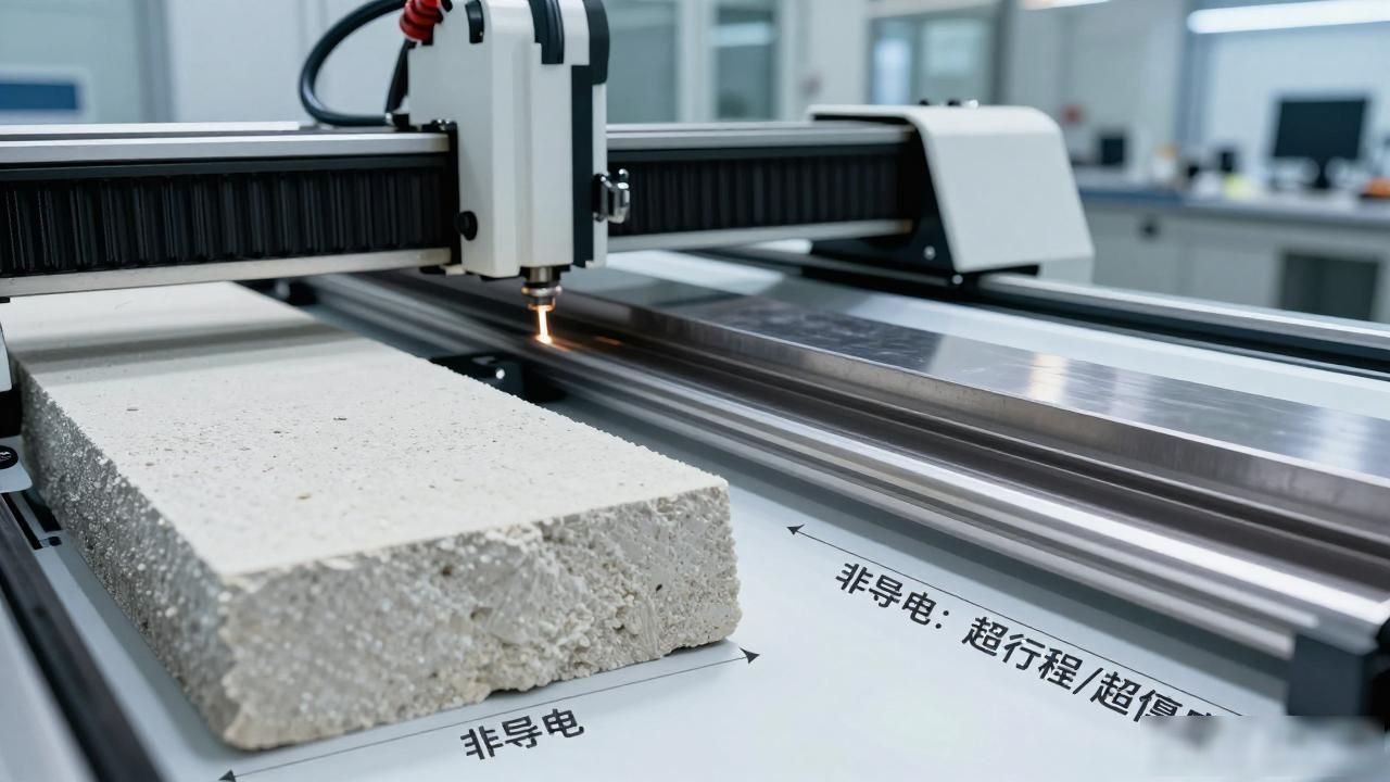
For non-conductive materials, wire cutting is completely impossible because the discharge circuit must be conductive. If the thickness of the workpiece exceeds the span length of the wire frame, or the processing length exceeds the effective stroke range of the XY carriage, and there are very high requirements for accuracy, these can only be abandoned directly.
Don’t be too stuck on accuracy and clearance.
The matching gap of the punching die is usually kept in the range of 0.02 to 0.05 mm, and the thickness of the punched workpiece is most common within 3 mm. If the gap is adjusted too tightly, the values generated by thermal deformation and wire diameter compensation will be superimposed, and the final error will exceed the standard limit. Therefore, it is necessary to communicate with customers in advance and confirm the tolerance range they can accept.
The precision requirements marked on the drawing are IT7 or above. In this case, it is difficult to achieve the wire cutting in one go. The usual practice is to leave a grinding allowance of about 0.05 mm to 0.1 mm. We should not put all this precision on the cutting step. We should leave room for subsequent processes, so that the overall effect is stable.
Several pitfalls that are easy to step into when programming
At the corner, a rounded corner will naturally form. The radius of this fillet is equal to the radius of the electrode wire plus half the size of the discharge gap. If we are using 0.25mm wire EDM wire, and the discharge gap is set to 0.03mm.
Then calculated, the radius of the fillet is 0.155 mm. However, because the engineering drawings require sharp corners, additional compensation must be added during programming operations.
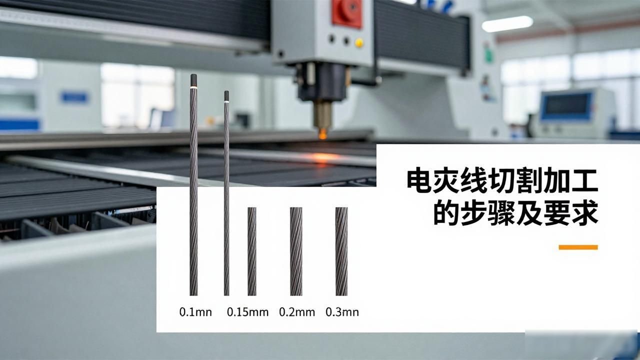
Before starting to write a program, the specifications of the electrode wire must be confirmed. Commonly used electrode wire diameters on the market include 0.1, 0.15, 0.2, and 0.3 mm. Once the wrong wire diameter is selected, the discharge gap will change accordingly. At this time, the entire cutting trajectory and feed speed need to be recalculated, which will cause a lot of time to be wasted on the machine.
The process route was set wrong and everything was done in vain.
In 2024, a mold factory in Suzhou fell into this situation. Because it directly carried out the programming operation without reviewing the drawings first, it was discovered after the cutting was completed that the size of the narrow groove was smaller than the diameter of the electrode wire, resulting in the entire piece of material becoming a scrap. The cost of materials alone cost thousands of dollars.
You must follow the order of reviewing the drawings first, then executing the programming, and finally going to the machine tool for processing. This order must not be messed up.
When equipment conditions are limited, first clearly distinguish what can be done and what cannot be done, and don't be greedy for too much. For parts that can be cut by conventional methods, machine them in place first. For some positions that cannot be conventionally cut, EDM or milling should be used for processing. If you force the processing, it will only make the problem more troublesome in the end.
Before the wire cutting process is carried out in your factory, the review of the drawings is usually handed over to a specific person, and in the actual production process in the past, have you encountered any adverse consequences caused by review errors? If you think this topic is valuable, you can like it and forward this content to your colleagues to watch.






No comments yet