


Although CNC is easy to use, do you know the common problems and solutions?
From the perspective of machine operation, there is absolutely no problem with the CNC machining center working continuously for more than ten hours a day. However, if the size is sometimes too large and sometimes too small, and the finish of the machined surface is very poor, then the result is that the entire batch of goods will be judged as scrap.
The following 9 fault conditions that occur very frequently have basically covered more than 90% of all scenarios involving abnormal dimensions that occur in the workshop.
Accurate size but rough surface

Although the dimensions are in place, the Ra value does exceed the standard. This phenomenon is probably due to the fact that the cutting edge of the blade is slightly chipped, and then the chips repeatedly scrape the machined surface during the machining process, which leads to this situation.
It is recommended that the operator carefully check the status of the tool after processing 30 products each time. If the wear of the tool exceeds 0.1 mm, the tool should be replaced with a new one immediately. In addition, if the concentration of the cutting fluid is lower than 6%, the cooling effect is not sufficient, which will leave traces of hot glue on the surface of the part.
In one case, the feed is too large, and the speed does not keep up. For example, when turning materials such as 45 steel, the feed is set to 800, but the given speed is only 3000. If the cutting depth is relatively deep, knife marks will be obvious on the surface. However, if the speed is increased to above 5000, or the feed quantity is reduced to below 500, the smoothness can be reduced by one level.

How to find the size and deviation of several millimeters
One end of the workpiece is larger than the other, so the clamping situation must be checked first. If the clamping force at the tiger's mouth is uneven, or the workpiece is not aligned, and the stress is released after processing, warping will occur.

The specific operation steps are to use a dial indicator to measure the runout of the end face. If the value exceeds 0.03 mm, a clamping solution needs to be changed. If necessary, an auxiliary positioning pin needs to be added to completely lock the degree of freedom.
The overall size is a few millimeters off, and there is a high probability that the tool setting contacts are offset or the zero point is set incorrectly. For example, the X-axis should be measured using the tool center. Although CNC is easy to use, do you know the common problems and solutions? , you use the tip of the knife, and the difference is several millimeters. When troubleshooting, rotate the spindle half a turn and re -set the tool , and then check whether the G54 offset value and the actual workpiece position are consistent.
The drive is normal but the size is erratic
The phase light of the driver is on, but the size display sometimes becomes larger and smaller again. You must focus on checking the feedback circuit of the encoder.
Because the wire harness is repeatedly bent in the drag chain, this causes changes in contact resistance, causing the position signal to have jitter interference of about one to two millimeters. If the feedback line is routed separately and kept away from strong current lines, this symptom will be alleviated.

Then look at the servo gain parameters. If the position loop gain is set too high, the tracking error will be amplified. Especially when processing thin-walled parts, the actual cutting depth will be tens of microns more than the programmed value. You should try to reduce the gain to 80% of the default value, and then run a complete processing cycle to see if the dimensional fluctuations are narrowed, and then make appropriate fine adjustments.
Reasons why arc processing is not in place
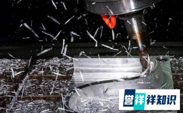
If it is an arc controlled by the two instructions G02 or G03, their error is between 0.1 mm and 0.3 mm. The most common reason for this situation is usually that the interpolation feed speed is limited.
You manually adjusted the feed rate to 80%, and then when the arc reached half way, the speed was directly cut off, and the actual trajectory deviated. You should pull the override back to 100%, remove the unnecessary G04 pause command, and then run the program again.

Another troublesome point is that the direction of tool radius compensation is reversed. If it is an internal arc, it is not clear whether to use the G41 command or the G42 command. The result is that the tool path is offset by a distance of the tool diameter, and the dimensional error becomes twice the tool radius value. When troubleshooting this problem, turn off the compensation function and run a program on the machine tool to see how far the cut tool mark differs from the theoretical contour. In this way, it can be determined whether it is a problem with the direction or an incorrect input of the tool radius data.

What should I do if the batch size is occasionally out of tolerance?
Among a hundred products, one or two defective products with particularly poor quality appear. The first step is to check the working status of the heat engine. Because the accuracy of the machine is completely different when it is first cold-started and after it has been running for two hours. Changes in spindle bearing temperature can cause positional drifts of two to five millimeters. Therefore, the spindle should be allowed to idle for 15 minutes before making the first product. Wait until the temperature has completely stabilized before starting work.
Let’s check the air pressure again. After all, the cylinder clamping relies on the pneumatic system. When the pressure value drops from 0.6 MPa to 0.4, the workpiece will undergo slight displacement and size changes. If a pressure gauge device is installed in the workshop, the alarm function will be triggered when the detected value is lower than 0.55 MPa. This can intercept most of the occasional out-of-tolerance problems, and its cost is far lower than the subsequent rework costs.
Increasing and decreasing signals for each process
The first cut is more accurate, the second cut is an extra strand of length, and the third cut is an extra strand of length. This is a typical thermal drift phenomenon. After the spindle motor heats up, its shaft will elongate, causing the actual length of the tool to become longer. We can turn on the FANUC thermal compensation function or MC54 function to compensate for 0.005 mm for every ten degrees increase in temperature, so that the cumulative error can be controlled.

If you find that there is a decline phenomenon, you should pay attention to see if the guide rail lubricant is not enough. When the oil film becomes thinner, the friction will increase, and the screw reverse clearance will be enlarged. Each process will shrink a little more than the previous one. Therefore, the guide oil should be replaced according to the maintenance cycle. Do not wait until the clearance is worn out before filling it, because then the accuracy will not be recovered.
What is the most common situation in your production workshop? You are welcome to tell us how you troubleshoot this process in the comment area. Please give it a like and save it so that you can directly check it next time.







暂无评论内容