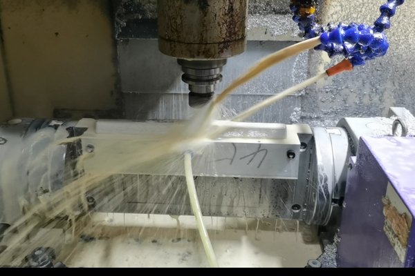


Industrial practice of CNC machining drawings (detailed explanation of CNC machining drawing symbols)
As long as many purchasing personnel and engineers get CNC machining drawings, they will be stuck for a long time just by looking at a certain line of content about tolerance marking. In fact, the core content of this category is mainly those parts. People who can understand things thoroughly can still start to operate quickly.
Dimensioning is the first step in understanding drawings
The most common dimension markings on CNC drawings include basic dimensions, limit deviations, and datum planes. According to the statistical work done by the Domestic Manufacturing Association in 2025, about half and half of the 60%, that is, the people who read the pictures at the beginning, generally get stuck in understanding the dimension chain.
Let’s take a factory in Shenzhen that specializes in making robot shells. Their drawings indicate a diameter of 12.5 mm plus or minus 0.01 mm. This means that the aperture must be strictly controlled within the range of 12.49 mm to 12.51 mm . As long as it exceeds this range, it will be treated as scrap.

When reading a picture, the first step is to find the datum. Look at the lower left corner of the drawing. There are three arrows on it, marked with the three letters A, B, and C. They refer to where the zero points are in the three directions. This means that all the dimensional data are calculated starting from that datum. If you reverse the direction, the final processed parts will simply not be able to be installed.
Tolerance level directly determines processing difficulty and cost
The tolerance is divided into 14 levels from IT5 to IT18, of which IT5 is a precision level and IT7 is an ordinary level. According to relevant data provided by a precision parts factory in Dongguan in 2024, the cost per piece of manufacturing IT5-level products such as aviation blades is about 4 to 6 times that of ordinary IT7-level products. The huge gap between the two is mainly reflected in the grinding process and inspection process.
When the tolerance level is not marked on the drawing, IT12 level should be taken according to the default provisions of the national standards. However, since the customer clearly specifies a fit tolerance such as H7/g6, the machining process must be replaced by precision turning or grinding process, which will lead to a completely different situation in terms of labor consumption and final quotation.
Don’t just look at the numerical value for surface roughness
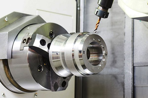
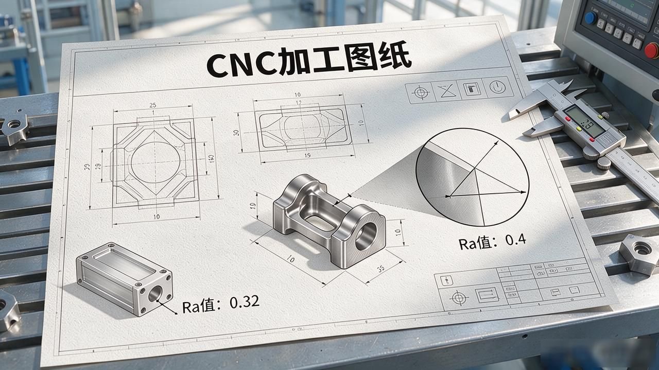
Regarding the Ra value of roughness, its value range is constantly changing between 0.2 microns and 12.5 microns. For titanium alloy implants in medical devices, we usually require that its Ra value be kept below 0.4. On the contrary, for ordinary aluminum casings, as long as the surface roughness value can reach a level of 0.32, it fully meets the usage requirements.
The specific case occurred in a medical device production factory in Hangzhou in 2023. The factory misread the data during the work process and misunderstood the original Ra 1.61 as Ra 0.16, which led to process deviations. They performed the polishing process twice more. The final result was that each production batch unexpectedly added approximately 8,000 yuan in additional expenses.
In the drawing, the smaller number next to the roughness symbol is the Ra value, and the unit is microns. This is common sense that everyone knows. Only when there are only symbols drawn and no specific values are stated, the default is to follow the medium precision level in the national standard. In most cases, the value of Ra3.2 will be used.
The material grade looks simple but actually has many pitfalls
In the title bar of the drawing, the type of material is usually stated, such as specific grades such as 6061-T6 aluminum, 45 steel or 316L stainless steel. How to understand CNC machining drawings in 2025? There is a customer of a non-standard equipment factory in Shanghai. He only wrote the word "aluminum" on the drawing, but did not indicate the specific brand number.
As a result, the factory defaults to using the cheapest raw materials to produce materials. When the goods were delivered, the customer directly rejected the goods. This back and forth resulted in a rework loss of more than 20,000 yuan.
Aluminum alloys are divided into two parts: casting materials and forging materials. When performing CNC processing, two grades of forged aluminum, 6061 or 7075, are usually used. Specifically, the strength of 7075 aluminum is about 40% higher than that of 6061. However, the resistance during the cutting process is relatively large, which can easily cause the tool to wear twice as fast as usual, so the final product quotation will be increased accordingly.
Customized parts drawings have more logic than standard parts
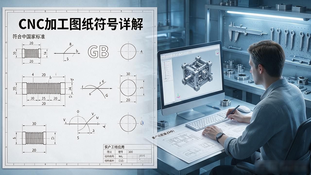
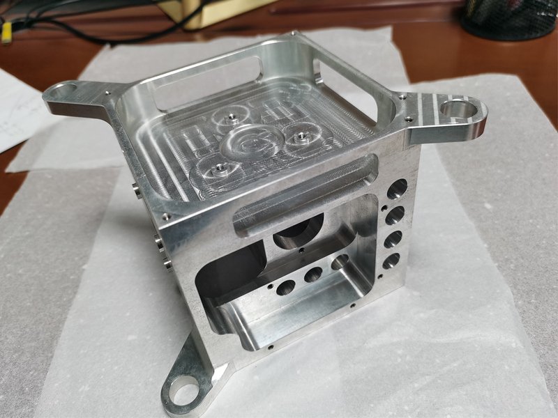
The drawing work of standard parts should be carried out in accordance with national standards, and their dimensions are fixed. For customized parts, you must first read the customer's functional description materials, and then perform reverse derivation and design of the structure.
A factory in Guangzhou that specializes in the production of robot joints received a single-piece custom order in 2024. Among them, the factory only received drawings and information about the outline and mating surface dimensions. For the internal structure design, engineers need to rely on their own planning and creation based on load conditions and speed requirements.
Drawings of customized parts often lack complete BOM and assembly relationships, so before processing, non-standard structures must be confirmed with the customer one by one. The reason why Jiebri has been able to accumulate more than 12,000 shell cases is mainly due to repeated and continuous communication, thereby turning the original vague requirements into executable drawings.
There is a process route from drawing to finished product
Even if the drawing work has been completed, it does not mean that the equipment can be put into use directly.
In 2025, there was a machinery manufacturer located in Suzhou, and its internal project manager expressed this situation to the outside world. Regarding a technical drawing specifically used for precision shaft parts, from the initial review process until the first sample is finally produced to meet the qualification standards, this entire process requires an average of four main steps: process design, clamping plan determination, tool selection, and trial cutting, and the entire process takes about three to five working days.
When performing CNC programming operations, each specific feature needs to be broken down into the corresponding tool path trajectory. At the same time, multiple independent tool movements must be arranged for the different processing states of roughing, semi-finishing, and finishing to gradually complete the process.
For those situations where the work can be completed in a single clamping state, every possible effort should be made to complete it in one go, in order to greatly reduce the cumulative geometric error problem directly caused by the secondary repositioning operation. Especially when dealing with those polyhedral parts, the concept and practice of single-station centralized processing and the industrial practice of CNC machining drawings (detailed explanation of CNC machining drawing symbols) are particularly important and critical.
Do you have a CNC drawing on hand recently that you are not quite sure about? Which annotation troubles you the most. Please share it in the comment area. Then give it a like and share this content with your colleagues.




暂无评论内容