

Why do various error problems occur in CNC machining? How to solve it?
If the accuracy of CNC machining is out of tolerance, the processing cost of the entire order will immediately increase significantly, and the delivery deadline must also be postponed. Next, the six most common causes of errors and their corresponding solutions will be explained clearly. The masters in the workshop can accurately locate the problem through comparison and investigation.
Unstable equipment levels cause large or small heads to appear on the workpiece
When the machine tool was installed, the leveling work was not completed, causing the base to be one side high and one side low. Therefore, during the process of cutting the long axis, taper problems occurred relatively easily. When the material is hard, if the knife is cut too deep, it will also aggravate the problem of big and small heads. Therefore, we must first use a level to level the equipment in all four directions, and keep the difference within <0.02> mm. Finally, the anchor bolts must be completely locked.
When performing hard material processing operations, the feed rate should be reduced to 70% of the usual standard value. It needs to be divided into two stages: rough machining and finishing machining. The purpose of this is to effectively prevent tool collision accidents.
After the entire processing process is completed, the specific values of the diameters at both ends of the workpiece are measured with the help of a caliper. As long as the measured difference does not exceed the tolerance range specified on the drawing, it will be deemed a qualified product. By handling it in this way, the goal of eliminating the phenomenon of big and small heads can basically be achieved.

Tool wear and machine creep drag down surface quality
After the tool tip is worn, the blunting phenomenon will cause the fillet size to become larger, and the surface roughness index will directly deteriorate. If the equipment is unstable during the initial installation process and the guide rails crawl during operation, vibration patterns will appear on the surface of the parts.
When staff are handing over operations between shifts, cleaning the guide rails and replenishing lubricants are basic tasks that need to be performed every day.
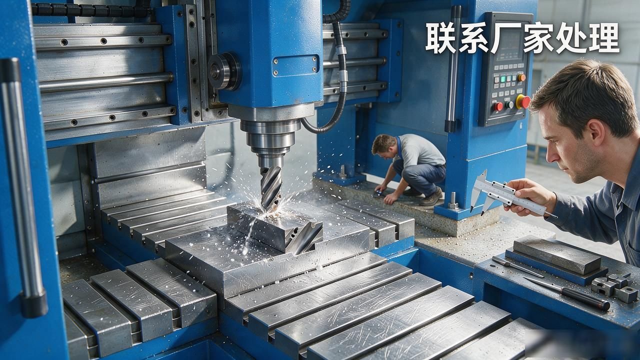
If you find that there are regular lines on the surface, you need to check the condition of the tool tip first. If the wear degree exceeds 0.1 mm, you need to re-sharpen it or replace it with a new tool. At the same time, you also need to check whether the footings and basic parts of the machine tool are loose. If you find that the guide rail is crawling seriously, you should contact the manufacturer's technical personnel to deal with the problem. Do not force the equipment to continue processing.
Spindle bearing wear causes processing dimensions to drift
Even though the phase light of the driver is glowing normally, the actual size data of the part still does not meet the correct requirements. This situation is most likely caused by the wear and deviation of the bearings inside the high-speed spindle. The operator should use a dial indicator tool to lean against the bottom of the tool holder and perform a fixed cycle program action to observe and analyze the performance of the pallet's repeated positioning accuracy performance index.
If the deviation exceeds the standard, adjust the gap between the screws. If you encounter bearings with serious wear, replace them directly.
After the replacement is completed, use a measuring tool like a dial indicator to carefully check whether the tool holder component can return to the starting position of the program very accurately. Only by controlling the error value during repeated positioning to within one thousandth of a millimeter can it pass the inspection.
Resonance and timing belt wear cannot determine the arc
When processing arc or spiral shapes, the dimensions often fail to meet the requirements. This situation is mostly due to the superposition of vibration frequencies, which causes resonance, or the timing belt is worn flat and slips. If the running speed of the stepper motor is set too high, it will also cause the problem of out-of-step and lost steps in the arc part.
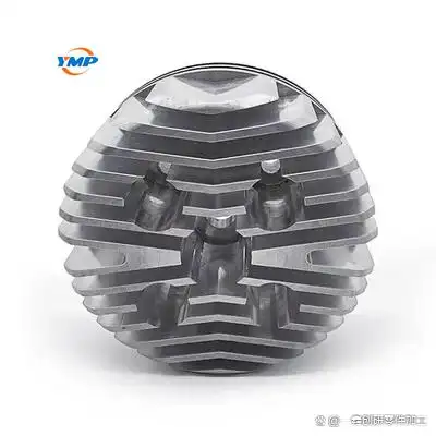
First, find the source of resonance, and then modify the processing speed to avoid that specific frequency. Also check the wear degree of the timing belt. If it is found to be aging, it should be replaced directly with a new one. In the arc segment, the feed amount should be reduced by two levels, and a smooth connection should be made inside the program segment to avoid step skipping.
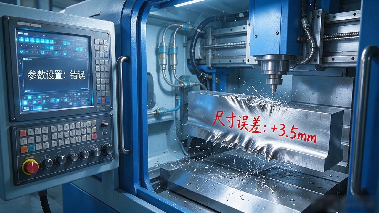
Too much rapid positioning and wrong parameter setting caused the size to be several millimeters different.
If the position of an axis deviates by a few millimeters, first check whether the G0 rapid positioning speed is set too high, which may cause the driver to be unable to respond in time. Next, check whether the screw bearing has become too tight due to wear or the tool holder is not firmly fixed, and whether the closed-loop operation is correctly set at the beginning and end of the program.
Reduce the G0 speed, reduce the cutting acceleration, and shorten the acceleration and deceleration time, so that the driver can operate within the rated frequency range. Then check the electron equivalence ratio and pulse layout parameters in the system. Be sure to confirm that the first part and the last part of the program are completely corresponding, and there cannot be any omissions.
Occasional deviations in batches and regular fluctuations in each process
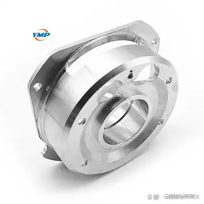
Most of this batch of parts are in a qualified state, but occasionally the dimensions of a few pieces are out of tolerance. Most of these situations are caused by the clamp not holding the workpiece firmly enough, or the system is subject to electromagnetic interference.
If the processing results of all processes deviate a little in the same direction, then this points to an error in the program instructions, or the system parameters have not been calibrated, or the transmission components have reached a period of periodic failure.
You need to add anti-interference capacitors and use shielded wires for isolation. You also need to check the firmness of the ground wire. In terms of program, it is necessary to check the execution trajectory line by line and calibrate the pulse equivalent and electronic gear ratio. For transmission components, once the maintenance cycle is reached, they need to be disassembled and inspected item by item.
What kind of accuracy error is the biggest headache in your factory? Chat in the comment area, like it and forward it to colleagues in the workshop if you find it useful.




暂无评论内容