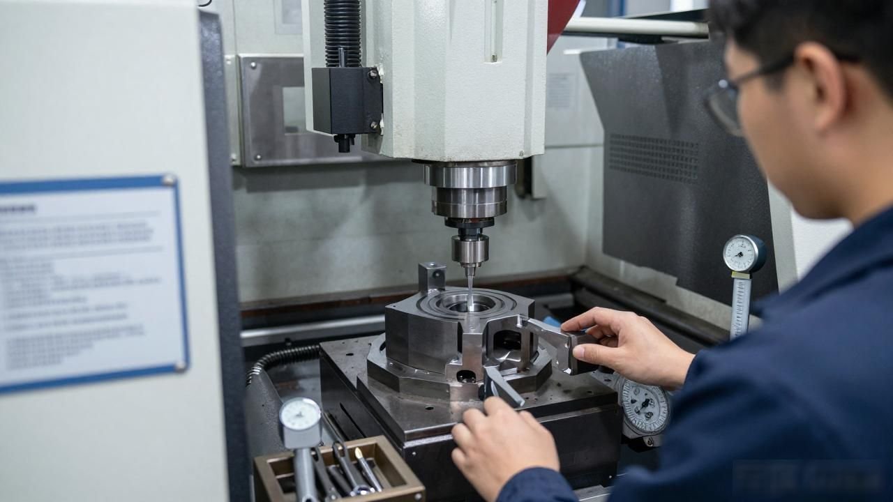


Five-axis machining center should pay attention to things when determining the specific positioning reference of parts
During the trial cutting of five-axis machining, if the positioning datum you choose is slightly offset, the accuracy of the entire batch of parts will completely collapse, resulting in rework costs that are even higher than scrapping the parts directly. As long as you step on the right points in the following five key links, you can achieve the clamping in place in one go. At this time, the pass rate of trial cutting can be increased to more than 90%.
Prioritize design basis
In the rough machining stage, the operator must clearly understand in advance how the fine benchmark should be ground and formed. For parts such as boxes, the operation process is to complete the milling of the bottom plane and two positioning planes on an ordinary machine tool to ensure that the dimensions are in place, and then install the workpiece on the five-axis linkage machining center, and directly use these three newly processed planes as positioning benchmarks.
The purpose of this operating mode is to avoid additional errors between 0.02 and 0.05 mm due to misalignment of the datums. The final effect is to save the complicated steps required for repeated tool setting operations in the subsequent process.
If a certain surface must be clamped three times or even need to be replaced by a machine tool before it can be processed, and if it is positioned according to the design basis each time, then there is no need to repeatedly convert the coordinate system in the program. In this way, the direct difficulty of programming will be halved, the probability of errors will be greatly reduced, and debugging time can be saved by two to three hours.
The key surfaces are clamped and punched in one go
Since the range of surfaces that a five-axis machine tool can process after one clamping is limited, those key precision parts should rely on the same benchmark as much as possible, and all processing operations such as screw holes, free hole chamfering, and non-important surfaces should be completed at one time. They should be processed after the finishing step. The advantage of this is to avoid bumps or even scratches during repeated circulation of parts. After all, every time a necessary process step is reduced, the corresponding risk will be reduced.

The process of the machining center is arranged at the last stage, and a margin of 0.3 to 0.5 mm is left in each previous process. Before finishing is required, the residual stress inside the workpiece has basically been completely released, so that the dimensional stability is at its best, thereby suppressing the probability of later deformation to the lowest level, which allows customers to pass the inspection in one go.
Two pins on one side are the most stable
For parts such as boxes and shells, two pins on one side are used to perform positioning operations, which can achieve optimal results in terms of stability.
The specific mechanism of this positioning method is as follows: Which side can limit the three translational degrees of freedom of the workpiece, and each of the two pins is responsible for limiting one rotational degree of freedom. As for the remaining longitudinal degree of freedom, it will be effectively guaranteed by the running path of the tool during processing and the corresponding programming, so that the workpiece will neither deviate in position nor flip over during processing.
The large pin controls the rotation and the small pin controls the translation. The diameter of the pin is set to 0.8 times to 0.9 times the diameter of the through hole. The reserved gap between the assemblies is controlled within the range of 0.01 mm to 0.03 mm. This will not cause the components to get stuck and at the same time maintain the positioning accuracy. This is a long-standing and very safe old rule in the production workshop. Five-axis machining centers should pay attention to when determining the specific positioning reference of parts. Novices are often most likely to make mistakes here.
Calculate the size chain before starting
When there is really no way to match the benchmark, do not force the process. You must first dig out the assembly drawings to clearly understand what functions the design basis performs. The dimensional chain must be calculated clearly, and the dead shape tolerance must be established between the positioning datum and the design datum. This value generally needs to be controlled within 0.03 mm. If it exceeds this range, the fixture must be replaced.
Five-axis machines with probes, such as the DMU 65 and the Haulfin 3X, require an inspection step using a probe in the machining program. Allow each workpiece to be automatically marked before being put on the machine.

Then the CNC system makes real-time corrections to the coordinate system. The purpose of this is to reduce the error to the level of 0.01 mm. In comparison, this method is ten times faster than manually holding a feeler gauge to set the knife.
Don’t leave programming zeros lying around
The origin position of this workpiece coordinate system does not necessarily have to be tightly pressed on the positioning datum, but there must be a certain geometric relationship between the two.
Most of the time, it will be selected at the center point of the bottom surface, or at a certain right-angled intersection. This is to facilitate manual operation to complete the tool setting work, and it is also easier to perform subsequent re-measurement operations with the probe. Moreover, it is relatively simple to convert coordinate values during the programming process, and it is not easy to write the wrong symbols.
For workpieces with high precision requirements, the origin must be directly measured through the positioning datum and must not be estimated by the naked eye. It is necessary to use a probe to detect the distance from the datum plane to the origin. If the deviation found exceeds 0.02 mm, the tool must be recalibrated.
This link must not be omitted. Once this step is omitted, the dimensions produced by subsequent processing will all deviate from the error situation, resulting in the trial cutting being completely in vain.
In your factory, what is the worst situation during the five-axis test cutting process? Is it because the benchmark selection is incorrect or because there is an error in programming? You are welcome to express your opinion in the comment area. If you think this content is helpful to your work, please like it and forward it to colleagues who work on the shift.







暂无评论内容