


How to adjust the pulse gap and width of wire cutting?
Wire breakage occurs as soon as the wire cutting equipment is started, and there are burrs on the cut surface of the workpiece. This is usually because the discharge pulse parameters are not properly adjusted according to the material thickness. If thick plates and thin plates use the same set of processing parameters, the production efficiency and surface quality will become very poor.
For thick workpieces, the pulse parameters should be increased.
When the thickness of the workpiece exceeds 5 mm, the discharge channel will become longer, and then the space for debris discharge will be reduced. In this case, we must increase the pulse width to at least 15 to 20 microseconds, and the interval time to 80 to 120 microseconds. The purpose of this is to ensure that aluminum chips and steel chips can be washed away after each discharge, thereby avoiding continuous short circuits or arcing.
In actual workshops, when cutting steel plates with a thickness of more than 10 mm, operators usually set the width parameter to about 25 microseconds and adjust the interval to 150 microseconds. As long as these parameters are sufficient, the wire speed can be stabilized at 15 to 20 mm per minute. In this way, the cutting workload of more than a dozen pieces per day will not cause wire breakage, and ultimately the work efficiency will be directly doubled.
Thin workpieces must reduce the discharge time
For aluminum parts or thin steel plates with a thickness in the range of 1 mm to 2 mm, the pulse width needs to be compressed within the range of 4 microseconds to 6 microseconds. At the same time, the interval time also needs to be shortened to a range of 30 microseconds to 50 microseconds.
Because the discharge time is relatively short, the heat-affected area on the surface of the workpiece will become smaller. In this way, the workpiece is relatively less prone to warping. Only in this case can the dimensional accuracy of cutting be maintained.
When cutting 0.5 mm thick copper sheets, some masters directly copy the parameter settings suitable for thick plates without analysis. This unreasonable approach eventually leads to the blackening of the surface of the cut workpiece. At the same time, defects such as chipping and chipping occur on the edges, and the degree of wear of the electrode wire increases sharply in a multiple.

Once the relevant process parameters of thin-walled parts are not adjusted just right, the economic loss value caused by a whole batch of materials being scrapped far exceeds the cost that can be saved by saving a little bit of processing time.
The material type determines the lower limit of the parameter
It is also 3 mm thick. Cutting aluminum alloy and cutting stainless steel are two completely different things. Aluminum material conducts heat very quickly and removes chips easily. The gap can be slightly narrowed. However, stainless steel material conducts heat very slowly and the debris is not easy to clean. The gap must be left for more than 20 microseconds, otherwise the cut surface will be completely black.
When using carbide, the operation will be more troublesome. This is because the hardness of the debris generated in the discharge gap is very high. This situation is very easy to scratch the electrode wire, so I suggest that the width should not exceed 12 microseconds. At the same time, you need to work with a relatively thin electrode wire such as 0.15 mm, and the current must be strictly controlled within the range of 3 to 5 amps. You can only bite the bullet and cut the workpiece slowly, and there is absolutely no rush.
Don’t ignore the electrode wire diameter
Compared with the 0.1 mm diameter molybdenum wire and the 0.3 mm diameter molybdenum wire, the gap between the width of the discharge channel formed by them is more than doubled.
When using a thinner metal wire to cut a metal workpiece with a thickness of 6 mm, the set interval must be at least 30% longer than the time required when using a thicker metal wire. Otherwise, the debris generated during the processing is likely to be blocked in the very narrow gap, resulting in continuous short circuit failures. This situation is inevitable.
On the other hand, if you use a wire with a diameter of 0.3 mm to cut a thin-walled part with a diameter of 1 mm, when the processing width exceeds 8 microns, the workpiece will be severely damaged to form a deep groove, causing the overall size to fail to meet the specified requirements and become seriously out of tolerance.
Because there is a mismatch between the diameter of the molybdenum wire and the thickness of the workpiece, even if the process parameters are set very accurately, it will not produce any actual effect. Therefore, it is necessary to confirm the specific diameter of the selected molybdenum wire before officially starting the cutting operation.
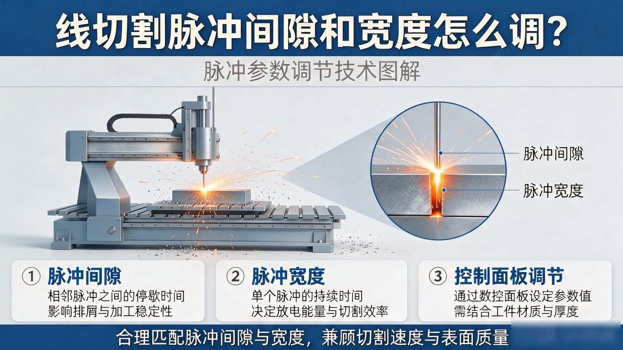
Cut surface burns and broken wires are parameter alarms
If the cut surface looks obviously black, the surface is rough, or even has tiny pits, this usually means that the energy of a single discharge is set too large, or the interval between the two discharges is set too short, resulting in the next discharge operation being carried out before the debris generated last time is washed away.
In response to this situation, it is recommended to reduce the pulse width parameter by 2 to 3 microseconds and increase the discharge interval time in the parameters by 10 to 20 microseconds. After this process, the cut surface will become smoother and cleaner.
The electrode wire frequently breaks at the same depth. This is most likely because the discharge interval is too short, which causes the local temperature of the electrode wire to be too high and become brittle. Therefore, the discharge interval needs to be increased to <20 microseconds>, and it is also necessary to check whether the coolant flow is sufficient. Because the two problems of too short a discharge interval and insufficient coolant flow often occur at the same time.
Coolant and electric current should be adjusted accordingly
The pulse parameter is not something that can be adjusted individually. When the high-speed wire cutting machine starts cutting, the coolant should be kept in the pressure range of 0.8 to 1.2 MPa. The chip removal mainly depends on the impact of the water flow. If the water pressure is low, the interval needs to be increased by an additional ten microseconds. This is to give the chips enough time to be washed away by the water flow.
When the cutting current is increased from five amps to eight amps, the single pulse energy directly increases by 60%, so the width must be shortened accordingly. Otherwise, the cutting slit will become wider and the surface roughness will soar. It is necessary to make linkage adjustments between the current, pulse and water pressure, and do not just focus on one parameter.
When you cut a workpiece with a thickness of 3 mm and a workpiece with a thickness of 10 mm in your production workshop, how many microseconds is the difference in the pulse interval parameter under normal circumstances? It is recommended that you report this specific value in the comment area. Wire cutting processing thickness range Wire cutting processing thickness range Wire cutting processing thickness range How to adjust the wire cutting pulse gap and width? So that others can compare and see the difference.








No comments yet