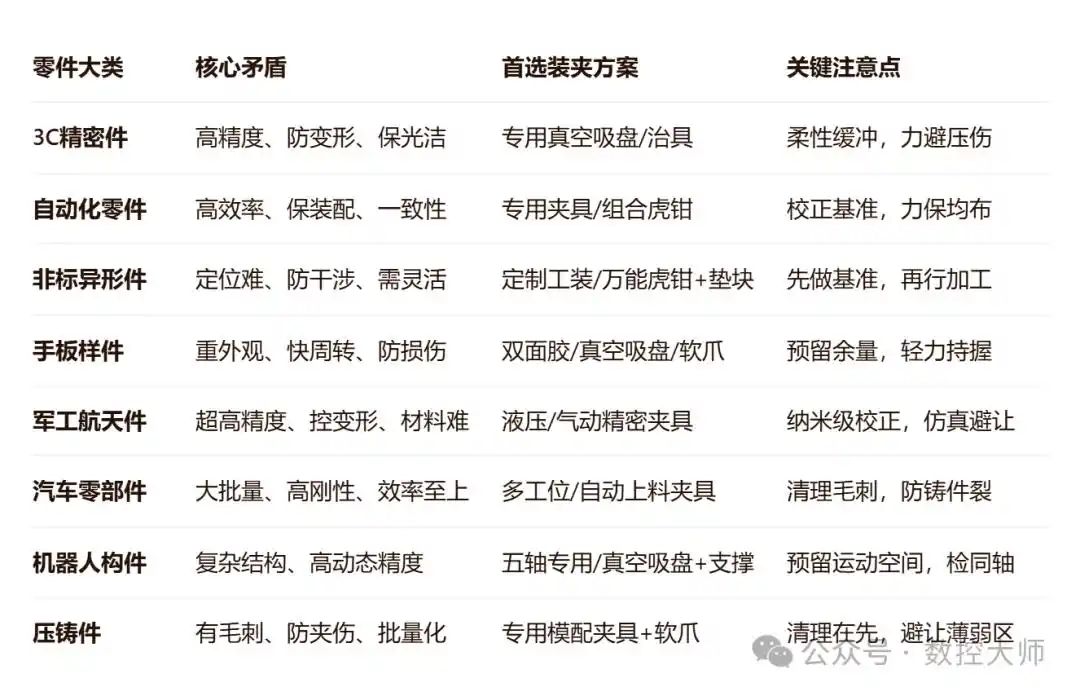


Complete explanation of CNC precision clamping process: from 3C micro parts to aerospace heavy equipment, a practical guide for clamping eight types of parts
If the work is not done well in the CNC clamping step, all subsequent processes will become meaningless and in vain. In many factories, workers often rely on subjective experience to fix parts at will. This behavior can easily lead to serious consequences such as parts flying out, surface collapse, and complete scrapping of machining accuracy.
Figuring out how to handle the setup of eight different types of workpieces has real benefits and practicalities far beyond simply purchasing more cutting tools.
Four iron laws of positioning and clamping
When you are clamping, you cannot avoid these four things. Specifically, the positioning must be accurate, the clamping must be firm, the deformation must be as small as possible, and there must be no interference. The first step is to select the main datum plane correctly, and then use a three-jaw chuck or vacuum adsorption method to fix it. The clamping force here needs to be controlled within the range of 0.3 to 0.5 MPa.
If the parts are thin-walled, it is recommended that you use wax gluing or polyurethane pouring instead of direct hard clamps to clamp them. Never use force to press the plate as soon as it comes up.

When selecting, you need to pay attention to three indicators, which are size, wall thickness and margin. If the thickness is less than 5 mm, then priority should be given to using vacuum adsorption or micro-glue dots. When the thickness reaches more than 20 mm, the fastening method of pressure plate and bolts should be used.
For those irregular-shaped parts, the correct approach is to first use 3D printing to create a special positioning tool, and then put it on the machine for processing. Never rely on subjective assumptions to guess or improvise.
3C and automated folder method
The wall thickness of the middle frame of a mobile phone is very thin, usually only 0.4 mm thick. When using a five-axis machine tool for processing, if the clamping force is too strong, the part will be deformed and eventually scrapped.
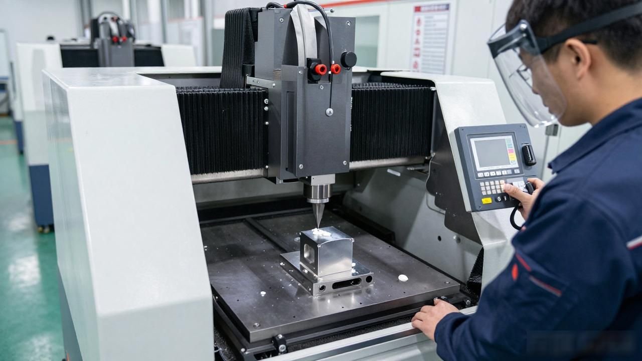
During the actual operation, everyone will use a vacuum suction disk with a small amount of glue dots to fix it. First, the speed must be increased to 25% of the normal value to conduct a trial cutting operation. Only after confirming that the part does not deform, can the speed be increased step by step until normal processing parameters are reached.
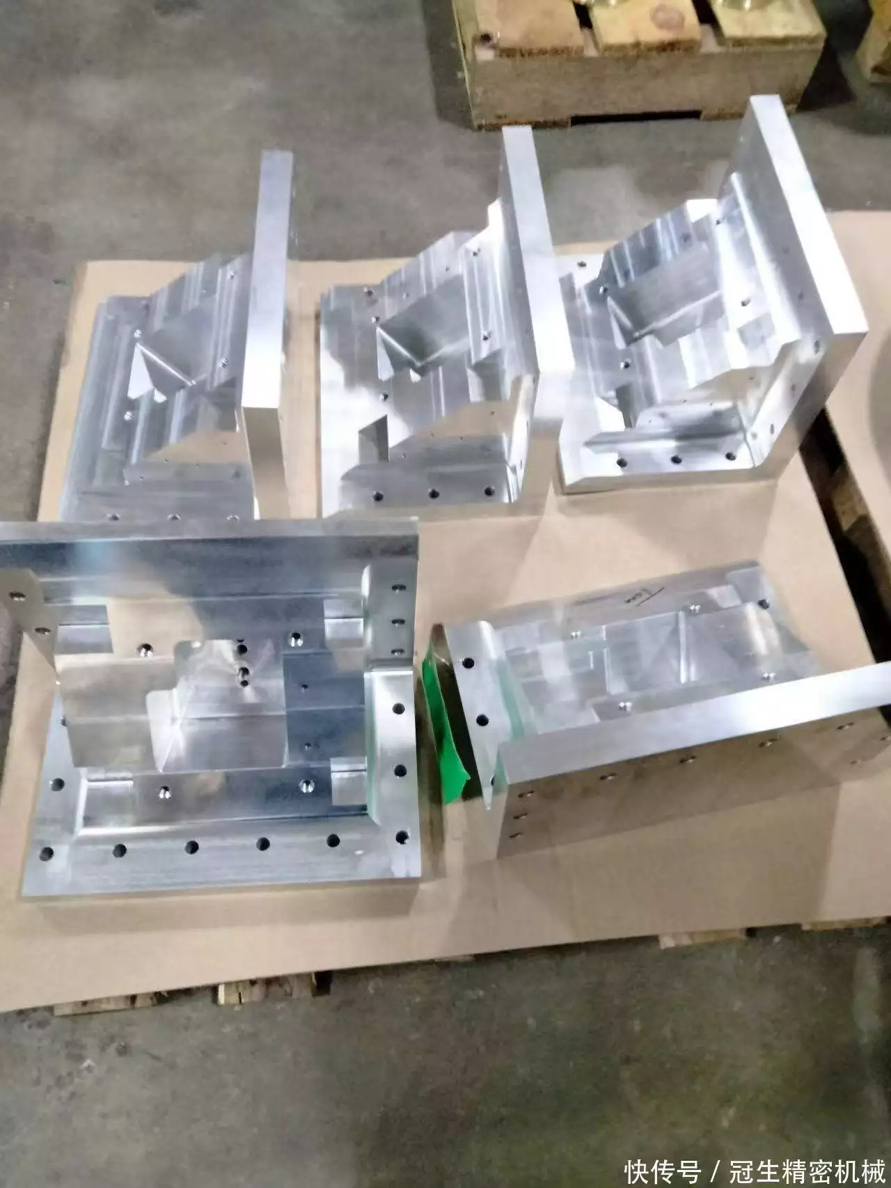
For automation structural parts such as guide rail seats and synchronization wheels, the focus needs to be on rigidity and rhythm. If the integral aluminum clamp is used to replace the bulk pressure plate, the processing of three surfaces can be completed in one positioning. At the same time, the changeover time can be compressed from the original 40 minutes to just 8 minutes, ultimately doubling the production line rhythm.
Non-standard parts and prototype parts clamping method
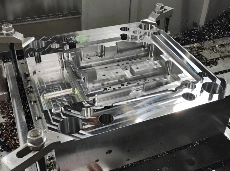
Because those parts that do not belong to standard types lack a unified standard reference system , each individual is unique in form or characteristics. The current core solution is to create a dedicated datum manually. The specific method is to first use milling processing to create two holes for positioning and a plane for positioning, and then all subsequent production and processing processes are all dependent on this temporary datum . Micro parts processing and clamping solutions . This saves time wastage caused by the need to determine the tool setting position during the machining process.
In the production of prototype parts, in order to meet the deadline and ensure that no clamp marks are left on the appearance surface, the method that can be adopted is to cast it with polyurethane or use a repeatable demoulding fixture to wrap the processed surface. At this time, only the areas that need to be processed are exposed.
After one curing operation, it can be completed within 15 minutes. The subsequent process is to spray oil directly on the surface, without the need for polishing.
Military and aerospace parts clamping method
The tolerances of turbine blades and satellite connectors are controlled within the range of two microns to five microns. The value of the clamping force must be calculated point by point. The amount of clamping deformation was repeatedly confirmed and measured using the three-probe six-point method.
The thin-walled section is processed by expanding the inflatable membrane, while the rigid section is held up by a hydraulic press. This is a situation that is absolutely not allowed to be processed using a simple and rough one-size-fits-all method.
The processing of aviation parts must be carried out based on the ABC surface marked on the drawing as the only reference. As for the gap between the clamping surface and that reference surface, precision gaskets need to be added for compensation.
After the installation is completed, the tool setting procedure must be completed completely, and a ball-nose tool must be used for the marking and confirmation operation. If the deviation is found to exceed the value of 0.02 mm, the clamping and fixing action must be performed again. This cannot be done with any compromising mentality.
Auto parts and robot parts clamping method
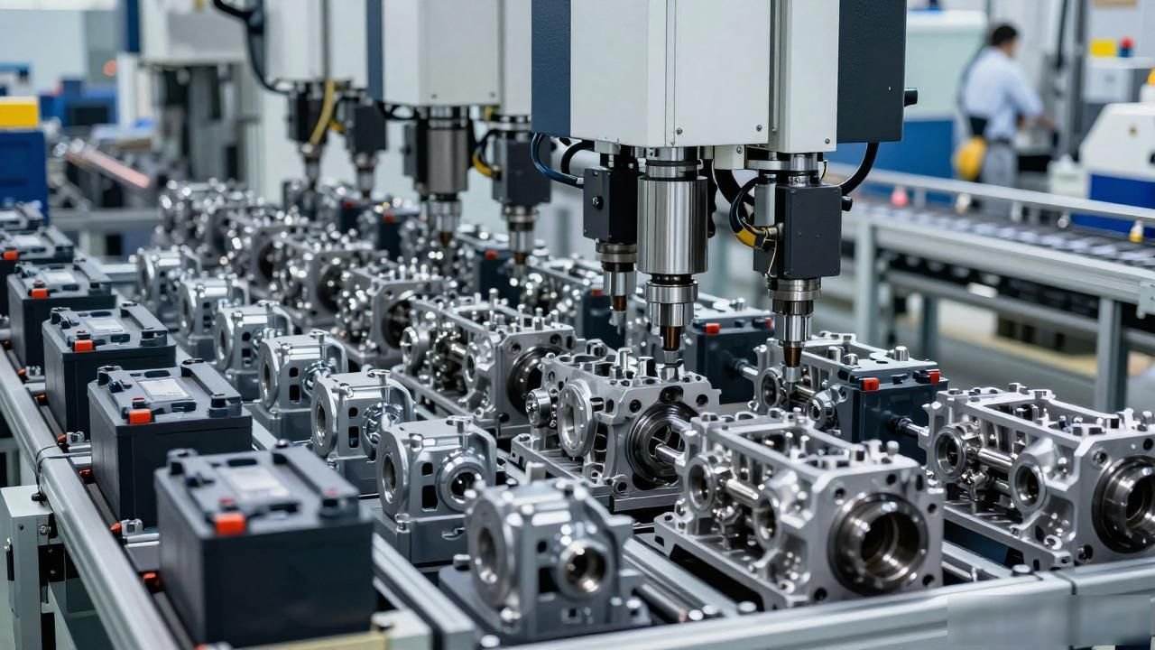
The cylinder block and the battery case are both mass-produced parts, so the core contradiction is reflected in the production rhythm. Under pneumatic control, 12 clamping points perform synchronous actions, and the entire process takes 8 seconds to complete a clamping operation.
There is a ball screw fine-tuning mechanism hidden inside the joint part of the robot, which can compensate for thermal drift in real time during processing. This can fundamentally ensure the stability, safety and reliability of dynamic accuracy.
Processing and clamping solutions for tiny parts such as hip joints and ankles of humanoid robots. Their structures are quite complex. When manufacturing, the gap problem during movement must be taken into consideration. With its contoured soft jaws, it hugs the original contours of the casting.
In this link, a margin of 0.1 millimeter needs to be deliberately reserved. This step is reserved for the subsequent finishing process. When the production batch becomes relatively large-scale, online measuring instruments should be installed and put into use. In this case, every product or every twenty products should be inspected to see if there is any attenuation of the clamping force.
Die castings and the ultimate mindset
When products such as die-casting parts are born, they are born with defects such as pores and shrinkage porosity. If they are pressed by directly applying hard force, they are particularly prone to cracking in these defective places.
So we need to first use X-ray inspection to mark those areas with defects, and then make all clamping points completely avoid these areas. When dealing with aluminum parts, we need to use an integral pressure plate to disperse the stress. When dealing with magnesium parts, we need to add an additional layer of rubber pad with a thickness of 2 mm to provide vibration isolation.
There is actually only one sentence in this set of mental methods, which means that when looking at parts, you must think clearly about what the function is, and when determining the benchmark, you must grasp the key points. When it comes to the mass production stage, it is necessary to pursue fast speed and high accuracy. When it comes to the precision machining stage, it is necessary to pursue stable operation and gentle process. When encountering irregularly shaped parts, special datums must be specially manufactured. When encountering difficult clamping situations, external forces must be used for help.
Of course, it is best to run a collision simulation check before installing the fixture. Testing must also be carried out after the first piece of clamping is completed. If these two steps are omitted, it will lay hidden safety hazards for the subsequent processes.
In your factory, which type of machined parts are most frequently subject to installation errors? You are welcome to leave a message in the comment area to describe the clamping method you use. Please give this content a like and save it for future use. When you need to clamp parts next time, you can take it out and check it.




暂无评论内容