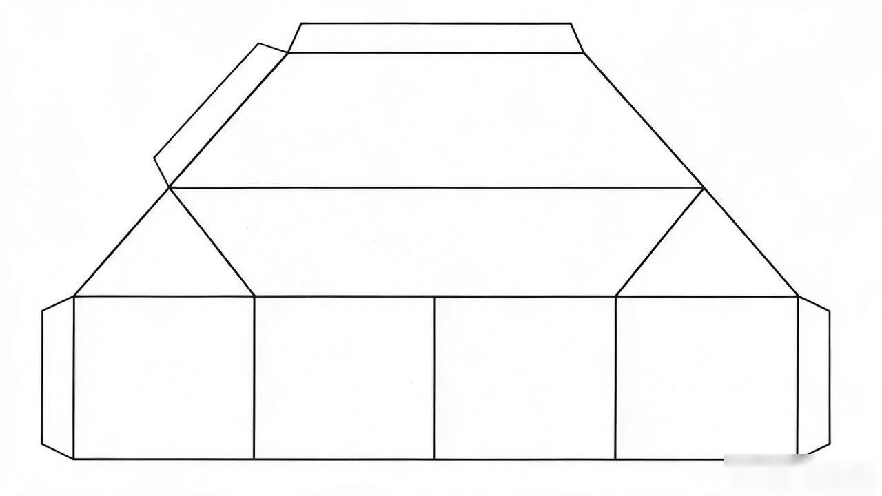


The drawing method of sheet metal unfolded diagram is very useful.pptx
When working in a sheet metal shop, if you unfold a piece of drawing wrongly, an entire piece of material will be scrapped. In fact, for things like the unfolded diagram of a three-dimensional surface, it is not as difficult as everyone thinks. The core operation in this process is to divide those curved surfaces into flat parts one by one, and then arrange them back in a specific order.
The difference between developable surfaces and non-developable surfaces
The surface parts of all polyhedrons are entirely composed of planes, which can be naturally expanded in nature. Among the surface bodies, only three types: cylinder, cone surface and tangent surface are judged to be developable surfaces. The reason is that the relationship between adjacent prime lines on these surfaces is either parallel to each other or intersects with each other, so it can be divided into several small planes for processing.
Shapes such as spheres and toroids are not expandable. When trying to expand them, it will inevitably cause the surface material to stretch or compress, thereby destroying its original form.
In the field of engineering, if we encounter a surface that cannot be expanded, we usually use the corresponding surface that can be flattened to make an approximation. It's like treating the shape of a spherical cap as a cone, or disassembling the structure of a torus and dividing it into several cylindrical sections.
For those parts that do not require particularly high precision, this is enough, and the error of the final cut material can be controlled within one millimeter.
The core idea of polyhedral expansion
The surface of a polyhedron is made up of several polygonal planes. The so-called expansion is to place these polygons one by one on a piece of paper according to their true shapes. Before you start drawing, you must first measure the actual length of each edge, and then arrange them according to the order of connection. When it comes to the joint, you must leave a little allowance for the thickness of the board.

Take the hopper as an example. The upper pyramid is surrounded by several triangular faces, while the lower prism is made of rectangular faces. If we could draw the true shape of each face, and then join them together one by one on the common edges, then a whole expanded picture would be created.
Expansion of prism normal section method
Each ridge line of a prism is parallel to each other. If a normal section perpendicular to these ridge lines is used to cut it, the resulting intersection line will become a straight line after expansion. Moreover, after expansion, all ridge lines will be perpendicular to this newly formed straight line. At the same time, the width of each face will be equal to the length of the corresponding line segment on that normal section in actual space.
During actual operation, we need to first draw the normal section intersection line, and then measure the length of each section to confirm that they are the real length status, and then arrange these things in the horizontal direction from left to right.
At this time, you need to make the top point correspond to the outline position at the top of the prism, and let the bottom point correspond to the outline position at the bottom of the entire structure. After the connection is completed, the true shape and specific conditions of each face can be fully displayed.
Example of hopper discharge pipe expansion
Given the front view and top view of the discharge pipe, first mark each edge of the prism. Make a normal section through the edge line AB, and take the actual length of each point of the intersection line. Expand the drawing and mark each point equally with a horizontal line.
In the process of unfolding the diagram, the points representing the true length should be arranged one after another, and then vertical lines should be drawn from each arranged point. These vertical lines are used to indicate the position of the ridges.
Next, the lines connecting the vertices must be connected neatly according to the specific shapes of the top and bottom of the discharge pipe, so that the production of the entire expanded diagram is completed. Finally, before carrying out the actual cutting operation, a two millimeter shear allowance needs to be reserved on the side for backup.
Approximate treatment of undevelopable surfaces
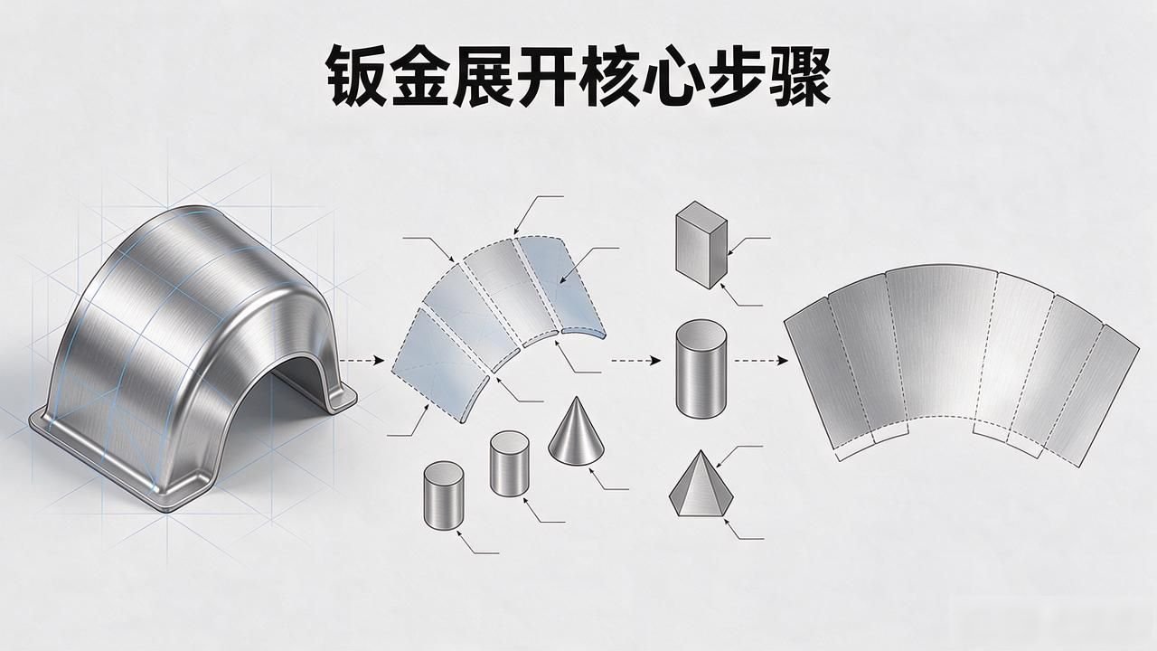
In actual situations, sheet metal parts rarely look like pure polyhedrons. Most of the ones we see are shells with curved surfaces. The way to deal with this kind of shell is to roughly divide the arc surface into several small plane segments, or to correspond to the small segments of the cylinder and the cone surface, and then unfold it segment by segment and finally put it back together.
When the segments are divided more densely, the error will naturally become smaller accordingly, but this will also exponentially increase and double the drawing time.
Empirically speaking, the angle of a curved surface segment cannot exceed fifteen degrees. After unfolding, its deviation from the original curved surface must be controlled within the range of 0.5 millimeters. If it is a welded part, you can roughly cut the material first, and then repair it; if it is a stamped part produced in large quantities, you must go through the mold trial process to verify whether the dimensions are correct.
The most common mistakes in drawing expanded diagrams
The most typical error is that the plate thickness compensation is not retained at all. There will be a plate thickness difference between the expanded size of the mid-surface and the expanded size of the plate. If a three-mm-thick plate is used without any compensation, the gap will become too large after the welding is completed.
Another common mistake is that the normal section is not really perpendicular to the edge line, resulting in a deviation in the angle, and the width of all faces will also change with this angle deviation.
In addition, some people confused the proportions of the unfolded diagrams and reversed one to one and one to five on the diagram, resulting in direct errors in the cutting process. We recommend that after you finish the drawing, you use a compass to measure several key side lengths and check it with the original drawing. Only after confirming that it is completely correct can you operate the shearing machine for processing.
In the actual work scenario where you personally draw the unfolded diagram, what type of three-dimensional surface is the most troublesome and troublesome to you? Is it a geometric shape like a pyramid or a shell structure with a curved surface that is more distressing?
Everyone is welcome to express your true thoughts in the comment area. If you think this paragraph is indeed useful to you, please like and save it, so that you will not panic the next time you face drawing these graphics.






暂无评论内容