

A method of making a riveting jig for medical CT machine embedded components
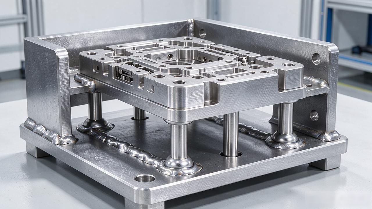
The riveting work of CT frame embedded components has always been an efficiency bottleneck in the production line. The speed of manual alignment operation is relatively slow, and the deviation rate of solder joints has always been at a relatively high level. This chassis fixture is equipped with dual hydraulic devices and a sliding structure, which can reduce the time required for a single clamping from fifteen minutes to three minutes.
Core problems solved by fixtures
The embedded components of medical CT machines involve a large number of precision riveted welding parts made of stainless steel. The plate thickness of these parts is usually 0.8 mm to 3 mm. In the past, it was very laborious to rivet the parts by hand. It often took fifteen minutes to install a clamp. The deviation probability of the solder joints has always been in the range of 3 to 5 thousandths, which slowed down the production rhythm of the entire production line. In addition, the cost of reworking defective products has also increased a lot.
This set of jig stacks the first and second workpieces together vertically, and clamps them simultaneously from both sides with a pair of hydraulic rods of the first hydraulic cylinder. The support plate supports the workpiece below from the bottom. Positioning, clamping and preventing rotation are completed in one clamping operation. Workers do not need to repeatedly fine-tune the clamping position, and the clamping time is directly reduced to less than three minutes.
Hydraulic positioning and clamping structure
On the upper surface of the machine base, a welded frame is installed. Inside this frame, a pair of first hydraulic cylinders are arranged transversely. From the sides of these hydraulic cylinders extend first hydraulic rods. There are two such rods, and the upper workpiece and the lower workpiece are sandwiched between them.
The hydraulic propulsion force can be infinitely adjusted according to the thickness of the sheet. Its maximum clamping force is approximately twelve thousand newtons. Therefore, stainless steel plates measuring 0.8 to 3 millimeters can be locked tightly and cannot move.
On the table of the machine base, use screws to fix the bottom end of the support plate and fix it tightly. There are many pairs of positioning holes on the upper surface of the support plate. The diameter of each positioning hole and its internal depth are in a one-to-one correspondence with the specifications of the rivet.

After the workpiece is placed, the rivets need to pass through these positioning holes from below. This action not only prevents rotation, but also provides an accurate reference plane setting effect for the subsequent pressure plate riveting work.
Chassis sliding and motor drive
On the top of the rack, the chassis is placed above the rails. On the inner part of this rail, work is done to form wheel grooves. At this time, there are two pairs of wheels embedded in these wheel grooves and in a rolling state. The wheels are connected in series by a connecting shaft, on which a pair of fixed plates are installed.
The function of this pair of fixed plates is to support the bottom of the chassis so that the entire chassis can slide along the front and rear directions of the wheel grooves. The sliding stroke is approximately 400 millimeters. Such a design can cover the needs of the main length direction of the riveting station.
There is a motor installed on the bottom surface inside the chassis. The output end of the motor is connected to a rotating shaft . This rotating shaft drives one of the connecting shafts to rotate through a belt transmission, allowing the connecting shaft to rotate. The entire chassis has the function of being moved by an external cart. At the same time, it can also rely on its own motor for fine-tuning of the drive, without the need for manual push and pull actions. The stop position can be kept consistent every time, so the rhythm of production operations becomes more stable and reliable, the operating load of the operator is also reduced, and the operator's work intensity becomes much easier.
The second hydraulic cylinder is riveted to the pressure plate
The second hydraulic cylinder is fixed in the middle of the bottom surface of the chassis. From the lower surface of the hydraulic cylinder, a second hydraulic rod extends. The end of this pole is connected to the pressure plate inside the frame.
On the lower surface of the pressure plate, there is also a pair of mounting plates. Through these mounting plates, the rivets are detachably installed. When the hydraulic rod is pressed down, the rivet will be pushed down together, thus penetrating into the workpiece, thereby completing the riveting operation.
The pressing plate is placed in the internal space of the frame, and its position is in the area directly above the superimposed surface of the first processing piece and the second processing piece. When the hydraulic rod presses down, the rivets will pass through the pre-opened holes on the two workpieces. At this time, the pressure plate will exert pressure on the tail ends of the rivets to cause them to undergo upsetting deformation, thereby forming a permanent riveted connection.
This process is completed in one go in the vertical direction. It is a method for making riveting fixtures for medical CT machine embedded components. There is no need to turn the workpiece over or transfer it to another station. Therefore, this method is particularly suitable for precision riveting welding of thin-walled stainless steel parts.
Limit design and overall stability
There is a limit hole in the middle of the top surface of the rack. Medical equipment (such as CT rack) is precision riveted with stainless steel . The horizontal span of the hole is exactly in the middle area of the two rails.
When the chassis slides to the riveting station, the above-mentioned limit holes will engage with the positioning pins installed on the surface of the chassis. This action can prevent the wheels from lateral movement when facing the force generated by riveting, thereby constraining the offset value of the workpiece in the horizontal direction to within 0.1 mm, thereby ensuring that the accurate position of the riveting point does not deviate.
The entire fixture extends from the base part to the chassis part, forming a closed frame structure. Its frame stiffness is very sufficient to withstand the lateral clamping force expressed in units of 1,200 Newtons, without causing any measurable deformation in the process.
If calculated based on the production of two to three hundred stainless steel precision riveted welding products per day, its repeatable positioning accuracy can remain stable within the range of plus or minus 0.05 mm during long-term use, so the rework rate will be significantly reduced.
In your workshop now, when the CT frame is performing riveting and welding operations, what level can the first pass rate reach?
We very much welcome you to chat with everyone in the comment area about the process parameters you use and how you select your equipment. If you think these shared contents are useful to you, please give it a like and forward it to your peers so that they can also learn about it.



暂无评论内容