Blog

  • On-site Riveting and Welding Techniques and Safety Regulations in Pipeline Installation and Maintenance

    On-site riveting and weldingPipework EngineeringSpecial challenges within
    Pipeline installation and maintenance frequently encounter constraints such as confined spaces, complex environments, and tight schedules, making on-site riveting and welding techniques pivotal to overcoming these challenges. Unlike factory settings, field welding must contend with variable weather conditions, diverse pipe materials, and heightened safety risks. This article delves into the core techniques and safety protocols for on-site riveting and welding, equipping engineering teams to enhance efficiency while ensuring accident-free operations.

    Part One: Preparations for On-Site Riveting and Welding
    Environmental Assessment and Risk Management

    Inspect the work area: Confirm the absence of flammable or explosive materials; position fire blankets and fire extinguishers.

    Weather Adaptability: A windbreak must be erected when wind speeds exceed 2 metres per second. Operations shall be suspended during rain or snow.

    Pipeline Pre-treatment Technology图片[1]-管道安装与维修中的现场铆焊加工技巧与安全规范-大连富泓机械有限公司

    Bevel machining: Employ portable beveling machines to ensure precision in both angle (typically 30-35°) and blunt edge (1-2mm).

    Cleaning procedure: Remove oil stains and rust using acetone or a specialised cleaning agent. Stainless steel pipes must be protected from contamination by carbon steel.

    Equipment and Materials Preparation

    Select lightweight inverter welders (such as the Miller Maxstar) equipped with generators.

    Welding consumables management: On-site use of welding rod insulation cylinders (maintaining 80–110°C) to prevent moisture absorption.

    Part Two: Core Techniques for On-Site Welding
    Welding strategies for different positions

    Horizontal fixed pipe (5G position): Employ segmented re-welding to control distortion, with each segment not exceeding 30 times the diameter of the welding rod.

    Vertical fixed pipe (2G position): Employ an upward weld to increase penetration depth, with interpass temperature controlled below 150°C.

    Inclined pipe (6G position): The most challenging position, requiring the use of oscillation welding techniques to maintain a constant arc length.

    Key Considerations for Welding Pipelines Made of Special Materials

    Carbon steel piping: Dry low-hydrogen electrodes (350–400°C × 1 hour), with controlled cooling post-welding to prevent cracking.

    Stainless steel pipework: Argon shielding at the rear (flow rate 5–10 L/min), employing rapid welding with low current.

    Alloy steel pipes: Strict preheating (in accordance with PQR requirements), post-weld heat treatment to relieve stresses.

    Defect Prevention and Emergency Response

    Preventing pinholes: Ensure the purity of the protective gas and inspect the gas lines for leaks.图片[2]-管道安装与维修中的现场铆焊加工技巧与安全规范-大连富泓机械有限公司

    Treatment for incomplete fusion: Re-weld after root cleaning using carbon arc gouging.

    Deformation correction: Restore straightness using hydraulic straighteners or flame straightening.

    Part Three: On-site Safety Regulations and Standards
    Personal Protective Equipment (PPE)

    Welding helmet: It is recommended to use an auto-darkening helmet (such as the 3M Speedglas).

    Protective clothing: flame-retardant workwear, insulating gloves, safety footwear.

    Respiratory protection: Use a powered air-purifying respirator (PAPR) in confined spaces.

    Work Permit and Supervision System

    Hot Work Permit: Specifies the time of operation, safety measures, and designated supervisor.

    Gas detection: Prior to commencement of work, test for combustible gases (LEL < 10% by volume) and oxygen concentration (19.5–23.5% by volume).

    Confined space operations: Mandatory ventilation, provision of escape routes, and equipping with rescue apparatus.

    Environmental and Community Protection

    Noise control: Employ noise barriers and avoid night-time operations.

    Waste management: Welding slag and discarded welding consumables shall be classified and recycled as hazardous waste.

    Part IV: Case Studies and Technological Innovation
    Case Study:Emergency Pipeline Repair at Chemical Plant

    Issue: Corrosion-induced leakage in DN300 stainless steel pipeline requiring pressure-welding.

    Solution: Employing Bell welding technology (through-hole plug welding) with Inconel 625 filler material, successful maintenance was achieved without production interruption.

    Trends in Technological Innovation

    Automated on-site welding: Rail-mounted welding robots (such as the Bug-O system) enhance consistency.

    Digital monitoring: Welding parameters transmitted in real time via IoT sensors for cloud-based analysis.

    Environmental technology: Low-fume flux-cored arc welding wire (FCAW-G) reduces environmental pollution.

    saada aikaan tuomio
    On-site pipe riveting and welding represents a synthesis of technical expertise, experience and safety. Engineering teams must continually update their technical knowledge, strictly adhere to safety protocols, and actively incorporate automated equipment and digital tools to execute operations efficiently and safely within complex environments.

  • How to Select a Reliable Aluminium Alloy Riveting and Welding Service Provider? Six Key Evaluation Criteria

    aluminium alloyRiveting and welding service providerThe Importance of Choice
    Aluminium alloys, owing to their lightweight, corrosion-resistant, and high-strength properties, are extensively utilised in aerospace, automotive manufacturing, and shipbuilding industries. However, welding aluminium alloys is prone to issues such as porosity, hot cracks, and deformation, placing exceptionally high demands on the technical capabilities of processing service providers. How does one select a reliable partner from among numerous service providers? This article systematically outlines six key evaluation criteria to assist you in making an informed decision.

    Standard One: Technical Qualifications and Industry Accreditation
    Essential certification

    ISO 9001 Quality Management System Certification: Ensures service providers maintain stable quality control processes.

    Specialised industry certifications such as Aerospace AS9100 and Automotive IATF 16949.

    Welding certification: such as AWS (American Welding Society) certified welders and EN 287 international welding qualifications.

    Equipment and Process Certification图片[1]-如何选择可靠的铝合金铆焊加工服务商?六大评估标准-大连富泓机械有限公司

    Equipped with specialised aluminium alloy welding equipment (such as AC pulsed TIG welders and reversible polarity plasma welders).

    The welding procedure qualification report (WPS/PQR) complies with AWS D1.2, the Code for Welding of Aluminium Alloys.

    Standard 2: Expertise in Materials and Processes
    Aluminium Alloy Series Identification Capability

    Distinguish between non-heat-treatable alloys (such as the 1xxx, 3xxx, and 5xxx series) and heat-treatable alloys (such as the 2xxx, 6xxx, and 7xxx series).

    Understanding the welding characteristics of different alloys: for instance, 5052 aluminium alloy exhibits excellent crack resistance, whilst 6061 requires strict control of heat input.

    Selection of Welding Processes

    Thin plates (<3mm) are best suited to TIG welding, while medium-thickness plates may be welded using MIG welding.

    For aerospace components, mastery of high-precision processes such as variable-polarity plasma arc welding (VPPA) is required.

    Standard Three: Quality Control System and Testing Capability图片[2]-如何选择可靠的铝合金铆焊加工服务商?六大评估标准-大连富泓机械有限公司
    process control

    Pre-welding cleaning management: Employ chemical cleaning or mechanical grinding to remove oxide films.

    Purity of protective gas: Argon purity must be ≥99.991% (three decimal places), and a dew point detector must be provided.

    Non-destructive testing capability

    Equipped with X-ray, ultrasonic, and penetrant testing apparatus.

    Provide test reports compliant with standards such as the ASTM E164 welding inspection standard.

    Criterion Four: Case Experience and Industry Reputation
    Review of Successful Cases

    Please provide examples of similar projects (such as automotive body welding or ship deck structures).

    Assess its performance on complex structures, such as irregular curved surfaces and butt joints between thick and thin plates.

    Customer Feedback and Industry Reputation

    Check company ratings through industry associations (such as the China Welding Association).

    Refer to customer reviews on third-party platforms (such as Alibaba Industrial Products).

    Criterion 5: Research and Development and Problem-Solving Capabilities
    Process optimisation capability

    Can welding parameters be optimised through DOE (Design of Experiments)?

    Addressing special requirements: such as developing low-heat-input processes to minimise distortion.

    Defect Analysis and Correction

    Provide microstructural analysis reports (SEM/EDS) for welding defects such as porosity and cracks.

    Possesses welding process simulation capabilities (such as using Simufact Welding software to predict deformation).

    Standard Six: Supply Chain and Service Level
    Delivery Capability and Lead Time

    Assess whether production capacity aligns with demand and whether the capability exists to handle urgent orders.

    Raw material procurement channels: Whether partnerships exist with renowned aluminium suppliers such as Alcoa and Chinalco.

    Myynnin jälkeinen palvelu ja tekninen tuki

    Provide welding technology training and on-site process guidance.

    We guarantee the quality assurance period and provide regular follow-up visits.

    Selection Process Recommendations
    Preliminary screening: Narrow down the selection to 3–5 firms based on qualifications and case studies.

    On-site audit: Inspection of factory equipment and quality control procedures.

    Specimen testing: Welded specimens must be provided for third-party inspection.

    Comprehensive assessment: Make the final decision based on quotation, delivery time and service.

    saada aikaan tuomio
    Selecting a reliable aluminium alloy riveting and welding service provider requires a comprehensive assessment across multiple dimensions, including technical capability, quality, and service. Enterprises are advised to avoid being solely price-driven, instead prioritising long-term technical compatibility and consistent quality to safeguard product performance and production safety.

  • Technical Requirements for Riveting and Welding of Special Materials in Pressure Vessel Manufacturing

    Special materials brazed under pressureforce containerthe pivotal role in
    Pressure vessels, as core equipment in sectors such as energy, chemical engineering, and aerospace, have safety and reliability that directly impact production safety and environmental protection. As industrial demands evolve towards extreme environments involving high temperatures, pressures, and corrosion resistance, the limitations of traditional materials become increasingly apparent. Consequently, riveting and welding processing technologies for specialised materials—such as high-strength steels, stainless steels, nickel-based alloys, and titanium alloys—have become critical components in pressure vessel manufacturing. This paper will provide an in-depth analysis of the technical requirements, process challenges, and industry applications of riveting and welding specialised materials, offering professional guidance for relevant practitioners.图片[1]-压力容器制造中的特种材料铆焊加工技术要求-大连富泓机械有限公司

    Part One: Properties of Common Specialty Materials and Welding Challenges
    High-strength low-alloy steel (HSLA)

    Characteristics: High yield strength, good toughness, but prone to cold cracking during welding.

    Technical requirements: Strictly control the preheating temperature (typically 150–250°C), employ low-hydrogen welding consumables, and perform post-weld de-hydrogenation treatment.

    Austenitic stainless steel (such as 304, 316L)

    Characteristics: High corrosion resistance, but prone to hot cracking and intergranular corrosion during welding.

    Technical requirements: Utilise ultra-low carbon welding consumables, control interpass temperature (<150°C), and employ argon arc welding shielding gas.

    Nickel-based alloys (such as Inconel 625)

    Properties: Resistant to high-temperature oxidation and stress corrosion, but prone to hot cracking and porosity during welding.

    Technical requirements: Thoroughly clean the grooves, use compatible welding consumables, and control heat input.

    Titanium and titanium alloys

    Characteristics: High strength-to-weight ratio, corrosion-resistant, but welding is susceptible to oxygen and nitrogen contamination.

    Technical requirements: Full inert gas shielding (back shielding), high-purity argon gas, thorough pre-welding cleaning.

    Part Two: Core Technical Requirements for Riveting and Welding of Special Materials图片[2]-压力容器制造中的特种材料铆焊加工技术要求-大连富泓机械有限公司
    Process Evaluation and Standard Compliance

    Must comply with industry standards such as ASME Section VIII and GB150.

    Welding procedure qualification (WPS/PQR) must cover all material thicknesses and joint configurations.

    Welding method selection

    Gas Tungsten Arc Welding (GTAW/TIG): Suitable for thin-walled and precision components.

    Gas Metal Arc Welding (GMAW/MIG): Suitable for efficient welding of medium to thick plates.

    Submerged arc welding (SAW): Suitable for longitudinal and circumferential welds on thick-walled vessels.

    Heat Treatment Control

    Preheating and post-heating: Prevent cold cracks and improve residual stress distribution.

    Solution treatment: Used to restore the corrosion resistance of austenitic stainless steel.

    Stress relief annealing: Reduces residual welding stresses and enhances dimensional stability.

    Non-Destructive Testing (NDT) Requirements

    Radiographic Testing (RT): Detection of internal defects such as porosity and lack of fusion.

    Ultrasonic Testing (UT): Suitable for detecting cracks in thick-walled vessels.

    Penetrant Testing (PT) and Magnetic Particle Testing (MT): Employed for the detection of surface defects.

    Part Three: Industry Application Cases and Trends
    Chemical reaction vessel

    Case Study: A polymerisation reactor lined with Hastelloy C-276 achieved corrosion-resistant layer welding through strip-welding technology.

    Nuclear power plant pressure vessel

    Case Study: Thick-walled welding of SA508 Gr.3 steel utilising narrow-gap submerged arc welding to enhance efficiency and minimise distortion.

    Trend Development

    Intelligent welding system: Integrated sensors monitor welding parameters in real time.

    Applications of Composite Materials: Plasma Cladding Technology for Metal-Ceramic Composite Coatings.

    Green Manufacturing: Application of low-fume welding consumables and high-efficiency welding power sources.

    saada aikaan tuomio
    The riveting and welding techniques for specialised materials in pressure vessel manufacturing demand exceptionally high standards, encompassing multidisciplinary fields such as materials science, process engineering, and quality control. Enterprises must establish comprehensive welding management systems, commit to sustained research and development investment, and cultivate highly skilled technical teams to maintain competitive advantage in high-end manufacturing.

  • How are machining quotes calculated? Top 10 Factors Affecting the Price of Parts Machining

    Received a copymachiningWhen quoting a price, have you ever been confused: how is this price arrived at? Why can the price of two seemingly similar parts be several times different? Transparent and reasonable quotation is the basis of trust and cooperation. This article will completely open the machining quote “black box”, detailed analysis of its cost model, and systematic combing of ten key factors affecting the final price, so that you from the “passive recipients” to “active evaluator! It allows you to change from a ”passive receiver” to an “active evaluator”, and even effectively control costs at the design stage.

    Introduction: Quotations are not magic, they are fine calculations

    Machining quotes are not arbitrary estimates, but are based on sophisticated calculations of resource consumption (time, materials) and process complexity. The core formula can be simplified as follows:

    Total part price = Material cost + Machining cost (man hours) + Outsourced processing costs + Management fee and profit.

    Of these, processing costs are the largest variable and are the focus of this paper’s analysis.

    Part 1: The four core cost components of a quote

    Cost of materials:

    Calculation: (net weight of part + processing losses) x unit price of material.

    Key point: Material utilisation is critical. Cutting a part from a standard-sized sheet or bar, the remaining “trim” cannot be credited to the next part at its original cost. Complex or fragmented nesting can lead to low utilisation and cost spikes. Supplier sourcing channels and inventory can also affect unit prices.

    Processing costs (labour hours):

    This is the core of the offer and the technical content. The formula for calculation is:

    Processing cost = preparation time x rate + processing time x rate

    Preparation time (one-off): Includes time for process planning, CAM programming, machine set-up, making simple fixtures and fittings, and first-piece commissioning and inspection. This cost is particularly significant for low-volume, multi-variety orders when it is spread over a single piece.

    Machining Time: The time the machine actually runs to cut. Calculated by CAM software based on accurate simulation of tool paths, or estimated based on experience. The hourly rate of a machine depends on its value (5-axis rate > 3-axis rate), depreciation, energy consumption and plant costs.

    Outsourced processing fees:

    After the parts are processed, if heat treatment (quenching, tempering), surface treatment (anodising, plating, painting, sandblasting), special processing (wire-cutting, EDM), etc. are required, this part will be completed by the supplier’s outsourcing or own department, and the cost will be listed separately.

    Overheads, profits and packaging and transport:

    Covers project management, quality control, business operating costs and reasonable profit. Formal quotations will clearly reflect this or include it in the labour hourly rate. Packaging and logistics costs are usually charged separately.

    Part II: Ten key factors affecting the price of parts machining (from most important to least important)

    Factor 1: Part complexity and number of features (determining factor)
    This is the most significant factor affecting machining time. A part covered with deep cavities, thin walls, complex surfaces, and tiny hole systems, compared to a simple square:

    Longer and more complex tool paths.

    More tool changes are required (different tools machining different features).

    Multi-face clamping or even multi-axis machining may be required.

    Programming and debugging time increases exponentially.

    Increases processing risk and may result in additional costs.

    Factor 2: Dimensional accuracy and geometric tolerance requirements
    The tighter the tolerances, the higher the price. An increase from ±0.1mm to ±0.025mm could mean:

    More sophisticated machine tools are needed.

    A slower finishing feed rate is required.

    Additional finishing processes need to be added (e.g. rough milling followed by finish milling, or milling followed by grinding).

    Requires more expensive testing equipment and longer testing times.

    Factor 3: Surface finish requirements
    Requirement of Ra 1.6μm vs Ra 0.4μm, huge cost difference. High finish requirement:

    Replacement of specialised finishing tools may be required.

    The feed rate must be reduced and the machining time extended.

    Separate processes such as polishing may need to be added.

    Factor IV: Number of orders (batch effect)
    This is the key to the cost per piece. Producing 100 pieces versus producing 1 piece:

    Programming and preparation time is dramatically diluted.

    Toolpaths and fixtures can be optimised for more efficient batch machining.

    Materials can be purchased in large quantities, reducing costs.

    The learning curve effect makes subsequent processing faster and faster.

    Factor 5: Selection of raw materials

    Material unit price: aluminium alloy, common steel, stainless steel, titanium alloy, PEEK plastic, the price difference can be tens of times.

    Machinability: Machining titanium alloys can take 2-3 times as long as machining aluminium alloys because lower cutting parameters, more wear-resistant tools and higher power consumption are required.

    Factor 6: Part Size and Weight

    Directly affects the cost of materials.

    Larger, more expensive machine tools are needed to accommodate them.

    Large workpieces are more difficult and time-consuming to clamp and lift.

    May exceed standard machine travel and require special equipment.

    Factor 7: Need for Workholding Fixtures

    Parts that can be clamped in a simple vise or platen at low cost.

    The need to design and produce special fixtures (e.g., for shaped parts) will result in a one-time tooling charge.

    Multi-face machining requires multiple reclamps, increasing time and risk of error.

    Factor 8: Post-treatment and special process requirements

    Anodising, hard oxidising, electroplating, laser marking, etc., charged according to the area or complexity of the process.

    Speciality processes (e.g. magnetic grinding, ultrasonic cleaning) also add to the cost.

    Factor 9: Supplier’s level of operation and geography

    Equipment sophistication: It may be cheaper to use a highly efficient 5-axis machine than to use a 3-axis machine to machine complex parts in multiple clampings.

    Process experience: Experienced engineers are able to plan better and less time-consuming process routes.

    Geographic manpower and operating costs: There are significant variations by region.

    Factor 10: Delivery time urgency

    Standard delivery prices are normal.

    Expedited orders may be subject to additional charges because it disrupts the normal production schedule and may need to be prioritised or scheduled for overtime.

    Part 3: How to get reasonable quotes and optimise costs? –Tips for Purchasers and Designers

    Provide clear and complete technical information: A standard 3D model (STEP/IGS) and 2D drawings with tolerances (PDF/DWG) are the basis. Vague requirements will inevitably lead to inflated quotations (in order to cover risks) or disputes at a later stage.

    Conduct Early Supplier Involvement (ESI) and DFM analysis: Send designs to experienced fabricators for review before finalisation. Their design for manufacturability recommendations can often lead to significant process simplification and cost reductions.

    For example: add a small rounded corner to avoid stress concentration in the sharp corner and facilitate tool machining; unify the hole diameter to reduce the number of tool changes; relax the tolerance of non-matching surfaces.

    Seek a transparent breakdown of the quote: Ask if the quote can provide an approximate percentage of the cost components (% of material, % of processing, % of outsourcing, etc.). This will help you judge the reasonableness of the price.

    Consider jobbing: If you have a variety of small parts, ask if you can “job shop” or “job shop” and share material sheets and machine setup time, which can dramatically reduce unit costs.

    Balance quality and cost: Define the end use of the part. A functional prototype for internal testing can have different accuracy and surface requirements, and should cost differently, than a part for the final product.

    Conclusion: A win-win situation built on understanding
    Machining quotation is a comprehensive art that combines materials science, process engineering and resource management. Understanding the logic behind it and the top ten influencing factors will not only enable you to read and understand the quotation, but also make you a cost control leader from the source of product design. The most successful co-operation comes from the customer’s respect for the logic of manufacturing and the supplier’s professional pursuit of the optimal solution to value.

    The next time you receive a quote, it is worthwhile to review each of these ten factors against each other. For any quotation, we promise to provide a clear explanation of the cost components and professional design optimisation suggestions, because we believe that transparent cost starts with professional design, and successful long-term cooperation starts with a deep understanding of each other. Welcome to hand over your design challenges to us, and let’s work together to find the best balance between quality, efficiency and cost!

  • From turning, milling, drilling to grinding – a comprehensive explanation of the common machining processes in machining.

    työstöThe world of turning and milling is a symphony of skills that use different “weapons” to shape materials with precision. The terms turning, milling, drilling and grinding may be unfamiliar to non-specialists, but they are the fundamental processes that have built modern industrial civilisation. This article serves as your panoramic guide to these four core machining methods, explaining in depth their principles, characteristics and application scenarios, and revealing how they work together to transform a rough blank into a precision part.

    Introduction: the “armoury” of machining”

    Each machining process corresponds to a specific class of machine tools, cutting tools and motion logic designed to solve manufacturing problems with different geometries. Understanding their essential differences is the first step in part design, process planning or supplier evaluation.图片[1]-从车、铣、钻到磨 – 全面解读机械加工中常见的加工工艺方法-大连富泓机械有限公司

    Part I: The Art of Turning – Turning Machining

    Core principle: The workpiece rotates and the tool feeds in a straight or curved line. Think of pottery drawing, where the blank rotates and the hand (tool) approaches to mould the shape. Turning mainly works on rotary features.

    Main machine tools: lathes, CNC lathes, mill-turn centres.

    Key motions: The workpiece performs the main motion (rotation) and the tool performs the feed motion (movement along the X and Z axes).

    Characteristics that can be processed:

    Bore: Cylindrical, conical.

    End faces/steps: The end planes of a part and the transition surfaces of different diameters.

    Thread: Internal and external threads (turned by synchronised movement).

    Grooving and Cutting: Ring grooving or final cutting of the part from the bar.

    Forming surfaces: Machining of complex rotary surfaces by means of forming tools or CNC interpolation.

    Process features and benefits:

    Efficient material removal: For shaft parts with a large L/D ratio, the efficiency is much higher than milling.

    Excellent coaxiality and roundness: High coaxiality is guaranteed as all features are machined around the same axis in a single clamping.

    Outstanding surface finish: excellent surface quality can be achieved by finish turning.

    Typical application parts: drive shafts, screws, bushings, flanges, nuts, hydraulic fittings, etc.

    Part II: Multifaceted Sculpting – Milling

    Core Principle: The tool rotates and the workpiece (or cutter) is fed in a straight line in multiple directions. Like a sculptor using a rotating carving knife to work on a blank. Milling is the workhorse for machining complex features on non-rotating bodies.

    Main machine tools: Milling machines, machining centres (vertical and horizontal), 5-axis machining centres.

    Key motions: The tool performs the main motion (high speed rotation) and the workpiece table (or head) performs the feed motion (movement along X, Y, Z and more axes).

    Features that can be processed (extremely wide range)

    Planes: Horizontal, vertical, oblique.

    Slots and cavities: Keyways, T-slots, various shapes of pits.

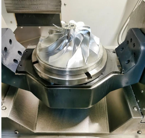
    Complex surfaces: mould cavities, impeller blades, ergonomic surfaces (depending on multi-axis linkage).

    Hole System: Although capable of drilling, it is more adept at machining multiple holes that require positional accuracy.

    Craft Classification:

    Face Milling: Highly efficient machining of flat surfaces using disc milling cutters with large surface area.

    End Milling/End Milling: Machining of flanks, slots, contours using end mills.

    Profiling: Machining of complex three-dimensional surfaces.

    Process features and benefits:

    Unrivalled flexibility: almost any geometry can be machined, making it a “jack of all trades” method.

    High precision and complexity: Multi-axis CNC milling machines enable micron-level precision and extremely complex features.

    Multiple processes in one clamping: Machining centres can automatically change tools for milling, drilling and tapping.

    Typical application parts: mobile phone shells, moulds, engine blocks, brackets, precision fixtures, shaped structural parts.

    Part III: Point Penetration – Drilling and Machining

    Core Principle: A process specifically designed to create round holes in solid materials. The tool (drill) makes both a rotary main motion and an axial feed motion.

    Main machine tools: drilling machines, lathes, milling machines/machining centres (more commonly used).

    Key motion: The tool rotates and advances in a straight line.

    Points to note:

    Centring and deviation: Ordinary drills tend to slide when cutting, resulting in deviation of the hole position. It is usually necessary to first make a precisely positioned guide pit with a centre drill.

    Hole accuracy and finish: Directly drilled holes have poor dimensional accuracy and surface finish and are usually used as a pre-machining process.

    Subsequent processes: For precision holes, reaming, reaming or boring is often required after drilling to improve dimensional accuracy and surface quality.

    Related Process Expansion:

    Reaming: The use of a reamer to make micro-cuts to existing holes to obtain high-precision, high-finish holes.

    Boring: The use of boring tools to enlarge or finish existing holes (especially large-diameter holes) and to correct deviations in hole position.

    Tapping: The use of a tap to machine internal threads in a hole.

    Typical applications: Holes in any part requiring bolted connections, shaft and pin positioning, fluid passages.

    Part IV: The Ultimate Finishing – Grinding Processes

    Core Principle: The use of a grinding wheel bonded with countless tiny, hard abrasive grains as a tool to make micro-cuts on the surface of a workpiece at very high linear speeds. This is a finishing process designed to achieve the ultimate in dimensional accuracy and surface quality.

    Main machine tools: surface grinding machines, cylindrical grinding machines, internal grinding machines, centreless grinding machines, tool grinding machines.

    Key movements: the grinding wheel rotates at high speed (main movement) and the workpiece moves at a lower speed (feed).

    Process features and benefits:

    Ultra-high precision: tolerances of IT5-IT7 and even higher (micron level).

    Excellent surface finish: Ra 0.1μm or less, achieving a “mirror effect”.

    Machinability of hard materials: the only or main means of machining hard materials such as hardened steel, carbide, ceramics, etc.

    Main Classification:

    Cylindrical grinding: Grinding the outer circle of shaft parts.

    Internal cylindrical grinding: Grinding the inner bore of sleeve-type parts.

    Surface grinding: Grinding of flat surfaces of parts.

    Centreless grinding: Highly efficient external grinding of small shaft components without the need for a centre hole.

    Typical application parts: precision spindles, piston rods, gauges, mould inserts, gear teeth, bearing races.

    Part V: Collaboration – Process Route Planning for Typical Parts

    A complex part rarely undergoes only one type of machining. For example, the manufacture of a precision spindle may involve the following steps:

    Unloading: Sawing machine to cut the bars.

    Rough ride: in图片[2]-从车、铣、钻到磨 – 全面解读机械加工中常见的加工工艺方法-大连富泓机械有限公司Make an approximate shape of the stepped shaft, leaving an allowance for finishing.

    Heat treatment: Tempering or quenching to increase hardness.

    Semi-finish turning/grinding of the centre hole: Preparation of the reference for subsequent grinding.

    Cylindrical grinding/centreless grinding: Grinding of all key bearing gears and mating cylinders to achieve the accuracy and finish required by the drawings.

    Milling: Machining of non-rotary features such as keyways on a milling machine or machining centre.

    Clamping: Deburring, chamfering.

    Conclusion: choosing the right “weapon”
    Turning, milling, drilling and grinding, the four main processes that form the cornerstone of machining. The choice of which or a combination of these depends on the material, geometry, accuracy requirements, batch size and cost objectives of the part.

    Choose a car for shafts and a mill for cavities.

    Drill the holes first and ream the fine holes.

    To be hard and light, it must be on a grinder.

    Understanding these basic processes will not only help you communicate better with your manufacturing engineers, but also allow you to consider the feasibility and economics of manufacturing from the design source (DFM). When you are faced with a complex part drawing, you may want to disassemble its features and think about its “process journey”. If you have questions about the process route of a specific part, please bring your drawings to us for consultation, and our process engineers will provide you with professional process analysis from blank to finished product.

  • Koneistusratkaisut ja kustannusanalyysit pienten erien ja useiden erilaisten tuotteiden prototyyppien valmistusta varten

    In the era of rapid product innovation, “fast” and “accurate” are the core demands of prototyping. When your needs are for small quantities (a few to hundreds of pieces) and many varieties (multiple design versions or different parts), the traditional scale production model is no longer applicable. How can you find a machining solution that ensures quality and accuracy while controlling cost and cycle time? In this article, we will provide an in-depth analysis of the solutions available for this scenario, a deep dive into their cost components, and a practical selection strategy.

    Part I: Unique Challenges and Core Requirements of Low Volume, Multi-Variety Prototyping

    First, identify the pain points of such projects:

    High mixing: Frequent part changeovers require reprogramming, machine setup, and tool and fixture preparation each time.

    Uncertain demand: Designs can be modified at any time, requiring a highly flexible and responsive supply chain.

    Cost sensitivity: Tooling and tooling costs cannot be amortised as they can in high volumes, and the cost of processing a single piece is a primary consideration.

    Time pressure: Tight R&D cycles require the shortest possible lead time from drawing to hand.

    Quality requirements are not compromised: prototypes are used for functional testing, assembly verification and even pre-release, and their accuracy and material properties must be consistent with the final product.

    The core requirements can be summarised as: flexibility, speed, affordable precision.图片[1]-小批量、多品种产品原型制作的机械加工解决方案与成本分析-大连富泓机械有限公司

    Part II: Four core solutions and their application scenarios

    In response to the above challenges, modern manufacturing offers several efficient solutions:

    Option 1: Digital CNC machining (mainstream option)

    How it works: Direct use of 3-axis/5-axisCNC-työstöCentres, programmed by CAM software, cut and form directly from standard blanks (plates, bars).

    Why it fits:

    No tooling costs: Directly driven by digital files for frequent design iterations.

    High material universality: engineering-grade materials (aluminium alloy, stainless steel, POM, etc.) that are consistent with mass production can be used, making test results authentic and reliable.

    High precision: excellent dimensional accuracy and surface finish are obtained directly, reducing the need for subsequent processing.

    Key to optimisation: Look for factories that use high-speed machining strategies, have quick tool change systems and automated fixturing (e.g. zero-point positioning systems) to significantly reduce changeover times.

    Option 2: Sheet metal processing + CNC secondary processing

    How it works: For shell and bracket parts, they are firstly undercut and bent by laser cutting / CNC punching to form the main body shape, and then CNC milling or drilling at key positions.

    Why it fits:

    Extremely efficient: For thin-walled parts, laser cutting is much faster than milling.

    Low cost: High material utilisation and proven process.

    Flexibility: Laser cutting drawings can be changed at virtually zero cost.

    Key to optimisation: Design with DFM (Design for Manufacturing) in mind to minimise the need for secondary machining.

    Programme III: Modular collaborative manufacturing and distributed production

    How it works: Utilise online manufacturing platforms (e.g. Xometry, Protolabs, domestic cloud factories) or local flexible manufacturing clusters. Upload your design files and the platform automatically analyses the process, quotes the price and intelligently distributes it to partner factories in its network.

    Why it fits:图片[2]-小批量、多品种产品原型制作的机械加工解决方案与成本分析-大连富泓机械有限公司

    Extreme Speed: Fully digital process, extremely fast quotes (minute by minute), utilising networked capacity, guaranteed delivery.

    No-touch efficiency: Ideal for standardised prototyping requirements with a clean process.

    Transparency in price comparison: Quick access to multiple virtual quotes.

    Note: For projects that are particularly complex, have special process requirements or require in-depth technical communication, it may be more effective to interface directly with a specialised factory.

    Option IV: 3D printing + CNC finishing (hybrid option)

    How it works: For exterior models or structurally complex non-load-bearing parts, industrial-grade SLA/DLP/SLS 3D printing is used to quickly obtain prototypes; for functional prototypes that require high precision, high strength, or specific materials, a “near-net-shape by metal 3D printing + CNC finishing of key features” approach is used.

    Why it fits:

    Coping with extremely complex geometries: This solution is economical when the part is so complex that CNC costs are prohibitive.

    Accelerated Iteration: 3D printing is unrivalled for speed in verifying form and assembly relationships.

    Key to optimisation: Clearly define the purpose of the prototype (whether it is a visual, assembly or functional test) and select the most economical combination of techniques.

    Part 3: Deep Cost Breakdown – Where are you spending your money?

    Understanding the cost components is the key to controlling your budget. A quote for a small lot of CNC machined parts usually includes:

    Programming and process design (one-off): This is a fixed cost that is incurred whether 1 or 100 pieces are made. Programming by an experienced engineer optimises the toolpath and saves machining time, and this is where the value of this cost lies. Multiple varieties means multiple programming fees.

    Material costs:

    Cost of raw materials.

    Material utilisation (nesting planning of plates/bars) is an important factor. Small and dispersed parts can be processed by plate joining to drastically reduce the cost of wasted material.

    Machining man-hours cost (machine tool running cost)

    Calculated at the hourly rate of the machine tool (covering depreciation of equipment, labour and electricity consumption).

    The time depends on: the volume of the part (amount of material removed), the complexity of the features (number of tool changes required), and the accuracy required (whether or not slow finishing is required).

    Clamping and set-up costs (per changeover): Includes time spent designing and producing simple tooling, mounting and calibrating. This is one of the main reasons for the high cost of small quantities of many varieties. The use of modular fixtures can significantly reduce this.

    Post-treatment and surface treatment costs: deburring, sandblasting, anodising, plating, etc., per piece or area.

    Quality Inspection Fee: Costs incurred for the first full inspection and issuance of the inspection report.

    A core strategy for cost reduction:

    Design optimisation (DFM): Early collaboration with process engineers to simplify processes, reduce the use of special tools, and relax non-critical tolerances.

    Order and Plate Machining: Arranging several different small parts to be machined on the same plate or machine table, sharing programming and setup costs.

    Selection of suitable materials and blank forms: Choose materials that are as easy to cut as possible and use standard profiles that are close to the final shape of the part (e.g., use thick plates rather than square milling).

    Part 4: How to Select and Evaluate Suppliers? –Checklist for Project Managers

    Choosing a good partner makes the project half successful. Please examine the following points of the supplier:

    Rapid Response and Collaboration Capability: Can design for manufacturability (DFM) feedback be provided quickly?

    Equipment Flexibility: Is it equipped with zero-point positioning system, quick-change tool magazine? Is the workshop clean and orderly (reflecting management efficiency)?

    Level of digitisation: Are quotes based on automated CAM man-hour estimates? Is the communication process clearly digitised?

    Small batch specialisation experience: Ask to see past examples of multiple small batches, not just large single parts.

    Transparent cost splitting: Does the quotation clearly list all the above costs? Transparent suppliers are more trustworthy.

    saada aikaan tuomio
    In small-lot, multi-variety machining, the competition is not for scale, but for flexibility, speed and fine cost management capability. The secret to success lies in intelligent DFM design optimisation on the front end and choosing a professional partner with digital management tools and a flexible production system on the back end. By understanding the cost structure and utilising strategies such as collocation and modular tooling, it is entirely possible to keep prototyping costs within reason without sacrificing quality and time. For those of you looking for an agile and reliable prototyping partner for your innovative products, our specially optimised low-volume rapid prototyping lines and professional DFM consulting services may be just the answer you need. Feel free to upload your first part drawings and let us provide you with a proposal that includes a detailed process analysis and transparent cost breakdown.

  • 3D-tulostuksen ja perinteisen työstön olennainen ero ja miten valita?

    At the crossroads of today’s product development and manufacturing, designers and engineers are often faced with a critical decision: should they use 3D printing orConventional machining (CNC)? Both are powerful techniques for transforming digital models into physical parts, but their philosophies, processes and areas of application are very different. This article aims to cut through the marketing jargon to reveal the essential differences between the two and provide a clear set of decision-making frameworks to help you make the optimal technology choice for any project.

    Part I: Philosophical Oppositions at the Roots – Enrichment vs. Reduction

    This is the cornerstone of understanding all distinctions.

    3D Printing (Additive Manufacturing): As the name suggests, it is an “additive” process. It builds parts by stacking materials (metal powders, resins, plastic filaments, etc.) layer by layer, similar to the idea of creating solids “from scratch” using calculus. It is centred on the idea of “free manufacturing” and is almost insensitive to geometric complexity.

    Conventional machining (subtractive manufacturing): its essence is “subtraction”. Starting with a complete solid piece of material (metal, plastic block), the cutting tool gradually removes the excess to obtain the desired shape. The core idea is “precision carving”, limited by the geometry and accessibility of the tool.

    This fundamental opposition draws out the differences between the two in almost every way.

    Part II: Multi-dimensional depth comparison: the game of capacity, cost and quality图片[1]-3D打印与传统机械加工的本质区别及如何选择?-大连富泓机械有限公司

    We can systematically compare the following key dimensions:

    1. Geometric complexity and design freedom

    3D printing (wins): This is where its revolutionary advantages lie. It can create virtually any shape imaginable, including those that are impossible with traditional methods: complex internal runners, honeycomb lightweight structures, integrated assemblies, organic bionic forms. Design is virtually unlimited, truly enabling “design-driven manufacturing”.

    CNC machining (limited): Limited by the linear and rotational characteristics of the tool. Closed cavities cannot be machined directly, deep and narrow grooves, complex internal geometries, negative angle features often require multiple clamping or special tooling, which can be costly or even impossible. The design must take into account “tool accessibility”.

    2. Material properties and isotropy

    3D Printing (Challenges and Opportunities):

    Material pool: The range is rapidly expanding to cover engineering plastics (nylon, ULTEM), photosensitive resins, metals (titanium, aluminium, stainless steel, nickel-based alloys) and even ceramics. However, specific grades and property states (e.g. heat treatment) often differ from those of the same grade of wrought material.

    Anisotropy: Due to layer-by-layer stacking, the bond strength between layers is usually lower than the strength within the layers, resulting in mechanical properties that may be directional. This is an issue that must be considered for high load bearing components.

    CNC machining (proven and reliable)

    Material library: Almost all machinable engineering materials are covered, from common steel and aluminium to high-temperature alloys, titanium alloys, brasses, engineering plastics (PEEK, PTFE), and so on. Standard profiles (plates, rods, tubes) are used, which are well established, with complete property data, and whose mechanical properties (obtained by forging, rolling) are usually superior and isotropic.

    Material Integrity: Machined parts retain the dense structure and excellent properties of the base material.

    3. Accuracy, surface finish and details图片[2]-3D打印与传统机械加工的本质区别及如何选择?-大连富泓机械有限公司

    3D printing (usually requires post-processing):

    Accuracy: Metal printing (SLM/DMLS) up to ±0.05-0.1mm, high precision resin (SLA/DLP) even higher. However, there are dimensional risks from shrinkage and warpage.

    Surface: Will produce a “step effect”, surface roughness (Ra value) is usually in a few microns to a dozen microns, the direct state (As-built) is rougher, often need sandblasting, polishing, grinding and other post-treatment to meet the requirements of use.

    CNC machining (native high precision):

    Accuracy: A benchmark for precision manufacturing. Standard CNC milling easily reaches ±0.025mm, and high precision machines reach micron levels. Extreme dimensional stability and predictability.

    Surface: Mirror-grade finish (Ra < 0.4 μm) can be obtained directly by fine milling and grinding processes. CNC is the default choice for high standard applications such as optics and seal fits.

    4. Production cost structure and economics

    3D Printing: Cost per piece has little to do with volume. Upfront costs are mainly in equipment and materials (specialised powders/resins are expensive). The economic model is: “complex is simple, simple is expensive”. Perfect for:

    Small lot/single piece complex parts (no tooling/tooling costs).

    Topologically optimised lightweight parts (saving expensive materials).

    Design validation prototypes with fast iteration rate.

    CNC machining: Costs are made up of “equipment depreciation + materials + labour hours”. The cost per piece decreases significantly as the volume increases (sharing programming and clamping time). The economic model is: “Simple is cheap, complex is expensive”. It fits perfectly:

    Medium to high volume production.

    Parts with relatively simple structures.

    Any batch that requires excellent surface and accuracy.

    5. Manufacturing speed and lead times

    3D Printing: Build time is proportional to part volume/height. Print one or a full version of a part with little difference in time. Good for parallel manufacturing of many different parts. For complex parts, may be faster than CNC programmed machining.

    CNC machining: Machining time is positively correlated to the amount of material removed. Small simple parts can be extremely fast. However, each new part requires separate programming and tooling preparation, with long first setup times, and is suitable for serialised manufacture of identical parts.

    Part III: How to choose? –Decision-making flowchart based on application scenarios

    Instead of asking “which one is better,” ask “which one is better for my specific needs?” . Follow the decision-making logic below:

    Examine the geometric complexity of the part:

    Does it contain integrated internal structures, extremely complex surfaces or topologically optimised shapes? → Priority is given to 3D printing.

    Is it a part that consists primarily of regular geometry (planes, cylinders, holes)? → Priority is given to CNC machining.

    Evaluate production lot sizes and cost targets:

    Need 1-100 pieces? And complex parts? → 3D printing is usually more economical.

    Need more than 500 parts? Or simple parts? → CNC machining will be more advantageous in terms of cost per piece.

    Verify material and performance requirements:

    Is isotropic high strength and toughness required? Or must you use a specific forging grade? → CNC machining is the safe choice.

    Are performance data sheets accepted and materials available in powder/resin form? Or pursuing speciality alloys/composites? → 3D Printing can evaluate.

    Consider precision and surface requirements:

    Assembly and sealing surfaces require Ra < 1.6μm or tolerances tighter than ±0.05mm? → CNC machining is preferred or as a means of post-processing finishing for 3D printing.

    As functional prototypes, internal runner parts or with general surface requirements? → 3D printing can be used directly or with simple post-processing.

    Part IV: Convergence and the Future – The Rise of Hybrid Manufacturing

    The most efficient solutions are often not either/or. Hybrid manufacturing is becoming the trend:

    3D Printing + CNC Finishing: Rapidly create complex blanks or near-net shapes with 3D printing, and then precision machine critical mating surfaces with CNC, balancing complexity with high precision.

    CNC Substrates + 3D Printed Features: Add complex features or repair worn areas to conventional parts with 3D printing (e.g. DED Directed Energy Deposition).

    Conclusion: complementarity, not substitution
    3D printing and traditional CNC machining are not rivals, but tools with different characteristics in the toolbox. 3D printing frees up design and excels in handling “impossible” geometries and small quantities of complex parts; CNC machining guarantees extreme precision and reliable performance, and excels in efficiently manufacturing “possible” regular parts and medium- to large-volume products. CNC machining guarantees extreme precision and reliable performance, and is good at efficiently manufacturing “possible” regular parts and medium- to high-volume products.
    A wise engineer will make rational trade-offs based on the five core elements of a project: geometry, materials, lot size, cost, and cycle time. For your next project, draw your part and compare it to the framework in this article, and a clear path will emerge. For challenging parts with both complex interiors and precise shapes, we also offer one-stop hybrid manufacturing solutions from 3D printing to 5-axis CNC finishing, so bring your 3D models along for a consultation.

  • Ranking-luettelo läheisistä koneistusvalmistajista - 2026 Viimeisin valintaopas ja kuopan välttämisneuvoja

    When your project is in dire need of a reliable työstö partner, “the best nearbymachine shopWhich one is it?” has become the most pressing question. The internet is full of “rankings”, but the real choice is much more than a simple list. This article aims to provide you with a practical, actionable and up-to-date 2026 selection guide, showing you how to identify truly professional and reliable local suppliers and avoid common pitfalls, just like the industry insiders do.

    I. Rational view of “ranking”: no absolute list, only matching standards

    First of all, let’s be clear: there are very few official or completely objective “ranking lists” in the machining industry. So-called rankings are mostly based on advertising investments, web activity or reviews of a limited sample. Your goal is not to find the “number one”, but to find the partner that “best fits your needs”. A small manufacturer specialising in precision medical devices may not be able to take on large structural steel parts, and vice versa.

    II. Five-dimensional assessment method: core screening criteria for professional buyers

    Forget fuzzy rankings and systematically evaluate potential vendors in the following five dimensions:

    1. Inventory of core technical capacity and equipment (hard-core inspection)

    Equipment sophistication: Ask to see their equipment list. Focus on the CNC brand (e.g. DMG MORI, MAZAK, Haas, etc.), the machining range (maximum stroke), and the availability of high-level equipment such as 5-axis machining centres and mill-turn machines. This directly determines the complexity and upper limit of accuracy of the parts they can handle.

    Process coverage: In addition to CNC, do you have complete supporting capabilities for turning, milling, grinding, wire EDM, heat treatment, surface treatment, etc.? One-stop service can greatly shorten your supply chain cycle.

    Measurement and QC Capability: Do you have high-precision inspection equipment such as Coordinate Measuring Machine (CMM), Quadratic Imager, Roughness Meter, etc.? This is the key evidence of whether the quality commitment can be put into practice.

    2. Quality control systems and industry certification (credibility endorsement)

    System certification: ISO 9001 certification of the quality management system is the basic threshold. If serving the automotive (IATF 16949), aerospace (AS9100) or medical industries, the corresponding special certification is essential.

    Process Control: Ask about their quality control process. Do they perform First Article Inspection (FAI)? Is there a comprehensive inspection report (IPQC/IQC)? How are critical dimensions monitored in the process?

    Technical team: Are there professional process engineers and programmers? Their experience directly affects machining efficiency and cost.

    3. Industry experience and success stories (match verification)

    Case Studies: Ask to see photos or videos of their past work, preferably in a similar product or industry to yours. The level of complexity and precision of the cases is more persuasive than the number.

    Client Testimonials: Look for testimonials from customers they have worked with for a long time, especially feedback on communication, problem solving, and delivery reliability.

    Trial capacity: For important projects, it is possible to offer to pay for a small trial run, which is the most direct way of checking their capacity.

    4. Communication responsiveness and service-mindedness (key to soft power)

    Speed of response: Is the response to your initial enquiry professional and timely? Can they make insightful process or design optimisation (DFM) suggestions for your drawings?

    Transparency in quoting: Does the quotation contain only a total price, or does it clearly list the breakdown of material costs, machining hours, tool sharing, surface treatment costs, etc.? Transparent quotes show professionalism and integrity.

    Project Management: Is there a dedicated project counterpart? Can you provide clear project timelines (e.g., programming, material preparation, machining, quality control, shipping)?

    5. Geographic location and capacity flexibility (practical considerations)

    “The real value of ”nearby”: geographic proximity facilitates face-to-face technical communication, emergency sample delivery, and rapid problem solving, which is especially valuable during the development phase.

    Capacity Match: Evaluate whether their current order load matches your demand volume. A small workshop may not be able to meet your high-volume needs, while a large factory may have little interest in small prototype orders.

    III. Guidelines for efficient sourcing and fieldwork operations

    Online search: Use “precision machining + your city”, “CNC machining + industry (e.g. automotive/medical)” and other combinations of keywords in Google, B2B platform search. Focus on browsing their official websites to see whether they are professional and whether the cases are detailed.

    Initial screening: Based on the above five-dimensional criteria, 3-5 interested manufacturers are screened.

    Initiate RFQ: Prepare a clear RFQ package including: detailed 3D drawings and 2D engineering drawings (PDF/DWG), material requirements, quantities, finishes, special criteria. Send it to candidate manufacturers to compare their response and professionalism.

    Site visit (highly recommended): For core suppliers, make sure to arrange a site visit. Observe whether the workshop is neat and orderly (5S management), the maintenance status of equipment, the working appearance of employees, and the management level of work-in-progress. Workshop environment is the most intuitive reflection of the management level.

    IV. Four key points of “pit avoidance” that we must be vigilant about in 2026

    “The ”low price trap“: offers that are far below market rates are often compensated for by cutting corners (e.g., using inferior materials), sacrificing precision, subsequent mark-ups, or poor service. ”Cheapest“ usually means ”highest total cost”.

    “The ”Jack of all trades“ trap: Factories that claim to ”do it all” often lack depth. Manufacturers that specialise in a particular process or industry usually have a technological and experience advantage.

    “The ”vague communication” trap: Suppliers who are vague about technical requirements and unwilling to confirm details in writing are extremely risky. All key requirements (tolerances, material certificates, inspection criteria) must be on paper or in a contract.

    “The ”lack of data” trap: manufacturers who cannot provide a list of equipment, test reports or evidence of past cases, their ability to describe the need to be greatly reduced.

    loppuhuomautukset
    Choosing a machining manufacturer is a strategic partnership based on a professional assessment. In 2026, the competition in the manufacturing industry is becoming more sophisticated, and your partner must have both hard and soft power. By abandoning the pursuit of illusory “rankings”, applying scientific evaluation methods, and taking the time to conduct in-depth investigations and communications, you can find a local manufacturing partner that you can trust to help your project succeed. A professional start is half the battle. When you are ready with detailed drawings and requirements, we are ready to visit you and provide you with a proven solution with our equipment list, case study library and transparent process.

  • Getting Started and Core Technologies: What is CNC CNC machining? Its working principle, types and core advantages in detail

    At the heart of today’s precision manufacturingCNC machiningLike a beating heart, it drives the creation of complex parts from smartphone components to aerospace engines. If you’re familiar with the term “CNC” but don’t know much about it, this article will give you a clear explanation: What is CNC machining? How does it work? What are the main types? And what are its irreplaceable core benefits.

    I. Definition of CNC machining: a digital bridge from blueprint to reality

    CNC, Computer Numerical Control, is a technology that automatically controls machine tools (e.g., milling machines, lathes, grinders, etc.) to perform precision machining through pre-programmed computer software instructions. In short, it is an automated process that converts a designer’s digital three-dimensional model (CAD file) into code (G-code) that can be understood by the machine, and drives precise movements of the machine tool or workpiece to “carve” the target part from a piece of raw material.

    The essence of CNC is “automation” and “digitalisation” compared to the traditional “manual machine tool” that relies on a human operator’s handle. It eliminates the inconsistencies and skill threshold limitations of human operation, making batch, high-precision manufacturing of complex geometries possible.

    II. The working principle of CNC systems: the three-step dance of precision

    CNC machining is not a one-step process, but an interlocking systematic project whose workflow can be divided into three core stages:

    1. Design phase: CAD modelling
    It all starts with computer-aided design (CAD). Engineers use software such as SolidWorks, AutoCAD or Fusion 360 to create a three-dimensional digital model of a part. This model defines all the geometric features, dimensions and tolerances of the part and is the “digital blueprint” for all subsequent operations.

    2. Programming phase: CAM conversion and G-code generation
    This is the “brain programming” part of CNC. With computer-aided manufacturing (CAM) software, the operator or programmer imports the CAD model. Within the CAM software, a number of key decisions are made:

    Process planning: Selection of the machine tool to be used (milling, turning or multi-axis machining centre).

    Tool selection: Matching the right tool to the different machining features (e.g. roughing, milling, drilling, tapping).

    Path Planning: Defines the trajectory of the tool relative to the workpiece, ensuring efficient, collision-free material removal.

    Parameter setting: Setting spindle speed, feed rate, depth of cut, etc.
    Once set up, the CAM software automatically compiles all this information into G-code, a standardised programming language containing coordinate points, movement commands and speed commands that are directly recognised by the machine tool.

    3. Implementation phase: machine tools
    The CNC controller (the “brain” of the machine) reads the G-code and accurately drives the servo motors. These motors control the movement of the machine’s axes (such as X, Y, Z, and even more rotary axes), allowing the tool to follow a set path and cut the material fixed to the table. The entire process is highly automated and usually only requires the operator to clamp the workpiece, set the tool and start monitoring.

    Mainstream CNC machine types and their application scenarios

    CNC machines are mainly classified into the following categories according to the mode of motion and machining characteristics:

    1. CNC milling machine: The most versatile type. The tool rotates at high speed and the workpiece is fixed on the table and cuts through a multi-axis linkage. Expertise in machining flat surfaces, grooves, complex contours and three-dimensional surfaces. Typical applications: moulds, housings, structural parts.
    2. CNC Lathe: The workpiece rotates under the spindle and the fixed tool cuts it radially or axially. It is good at machining cylindrical, conical and other rotary parts. Typical applications: shafts, screws, joints, flanges.
    3. CNC machining centre: Can be regarded as an “upgraded milling machine”, usually refers to CNC milling machines equipped with automatic tool changers and tool magazines. It can complete a variety of processes such as milling, drilling, boring, tapping, etc. in a single clamping, with high efficiency.
    4. Multi-axis CNC machines: e.g. 5-axis machining centres. In addition to the three linear axes, the tool or workpiece can move in two rotary axes. This makes it possible to approach the workpiece from almost any direction and to machine extremely complex geometries without the need for repeated clamping, making it a great tool for the manufacture of complex parts such as aerospace blades, impellers and high-end medical devices.
    5. Other specialised CNC equipment: e.g. CNC electric discharge machines (EDM), CNC laser cutting machines, CNC grinding machines, etc. for specific material and process requirements.

    Four, CNC numerical control machining unparalleled core advantages

    Choosing CNC machining means choosing a manufacturing solution that combines precision, efficiency and flexibility:

    1. Extraordinary accuracy and consistency: CNC machines have positioning accuracy down to the micron level (0.001mm). Once a programme has been validated, it can produce thousands of parts with identical dimensions around the clock, eliminating human error, which is critical for quality control.
    2. Ability to handle extremely complex geometries: With multi-axis linkages and advanced CAM software, CNCs can easily machine complex surfaces, cavities, and shaped structures that are virtually impossible to achieve by hand or with conventional machines.
    3. Superior repeatability and scalability: Digitised programs can be saved, recalled and optimised. Whether you are producing 10 prototypes or 100,000 parts, you only need to call the same programme, ensuring absolute consistency throughout the product lifecycle and a seamless transition from prototype to series production.
    4. Increased productivity and safety: Automated, continuous operation reduces set-up and tool change times (especially on machining centres) and allows operation in dimly lit “lights out shops”. At the same time, operators are kept away from the cutting area, which significantly improves production safety.
    5. Optimised material utilisation and cost control: Material waste can be reduced through intelligent tool path planning. Although the initial investment in equipment and programming is high, the cost-per-piece advantage is significant in medium to high volume production and optimises total cost of ownership in the long term by reducing scrap and rework.

    loppuhuomautukset
    CNC machining is a cornerstone technology of modern manufacturing, not only as an automation tool, but also as a sophisticated bridge between virtual design and the physical world. Understanding how it works, the types and benefits will help you make more informed decisions about product development or manufacturing outsourcing. Whether you need to prototype a precision part or plan for mass production, CNC technology provides a powerful, reliable and efficient solution.

  • Equipment & Costs: Automated Rivet Welding Processing Equipment Prices, Advantages & ROI Analysis

    Automated Riveting Equipment, Welding Robot Prices, ROI Analysis

    Article Outline:

    Introduction: In the face of rising labour costs and consistent quality requirements, is automation the way to go for riveting and welding factories?

    Mainstream automated riveting equipment types:

    Welding robot workstations: Flexible, suitable for multiple varieties and small batches.

    Specialised automation machines: Highly efficient for specific products such as automotive components.

    Automatic Riveting Machine: Precise control of riveting force and stroke.

    Cost components are detailed (give approximate ranges):

    Equipment acquisition costs (core): Robot body, shifter, welder, riveting unit, safety fence.

    Integration and programming costs.

    Ancillary facility costs: foundations, electricity, gas supply.

    Post maintenance and consumable costs.

    Five core benefits from automation (quantitative elaboration):

    Efficiency gains: Increased output per unit of time.

    Consistency of quality: Human fluctuations are virtually eliminated.

    Reduced reliance on senior technicians: Programming and maintenance staff have different needs.

    Work environment improvement and safety enhancement.

    Flexible production capacity: fast product changeover.

    Return on Investment (ROI) simulation calculation:

    Assume a scenario where there are five welders at a workstation.

    Calculated inputs: Total equipment inputs.

    Calculated savings: labour cost savings, rework reduction savings, additional benefits from increased capacity.

    Give the payback period formula and an example.

    Challenges and Recommendations for Automation Transformation: High initial investment, need for skilled people, products need to be of a certain volume or repetitive nature.

    Conclusion: Automation is not an end in itself, but a means to improve competitiveness. For companies with stable orders, the return on investment is clearly visible.

    Call to Action: We can provide automated production line planning consultancy and equipment selection services, with free capacity assessment by appointment.