
How is the core load-bearing structure of the bridge crane designed?
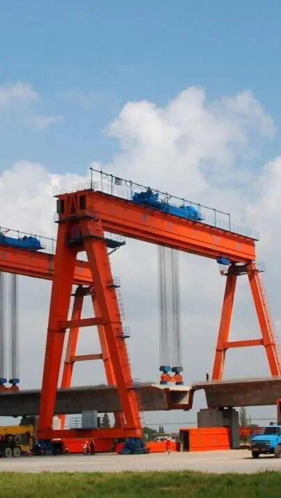
Why does the box-type double-girder structure become the mainstream choice?
The bridge frame used for bridge cranes is usually made of two parallel main beams that are welded to the end beams to form an I-shaped frame; the main beams are designed with a box-shaped section. Such a structural form can effectively resist torsional forces and is especially suitable for use in large-span workshops. The welding process of the box structure is a relatively mature crane structure that combines high-strength bolt connection and welding . The factory can carry out mass production, and in the later stage, it is more convenient to maintain.
The box-type double girder can be adapted to different lifting capacity requirements by adjusting the thickness of the plate. It can not only carry out lightweight design, but also increase the load-bearing capacity. For example, data presented by a crane manufacturer shows that after adopting a box structure, the amount of steel used is reduced by about 15% for the same span, and at the same time, the torsional performance is improved by more than 30%.
How material selection balances strength and cost
Commonly used as main beams are Q345 or Q235 low-alloy high-strength structural steel. These two materials can ensure sufficient strength and good toughness. The end beam adopts a box-shaped structure made of tailor-welded steel plates. With the help of segmented modular design, the manufacturing difficulty and transportation cost are reduced.
In an actual project, a crane manufacturer used a crane structure that was a hybrid of Q345 steel high-strength bolted connections and welding on a 31.5-meter-span bridge, and combined with high-strength bolted nodes, ultimately reduced the weight of the overall structure by about 8% compared to a pure welding solution. Such a combination of materials and connection methods effectively controlled manufacturing costs while ensuring safety.
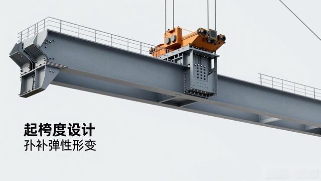
The camber design on the main beam reduces running resistance

During lifting, a crane structure with a mixture of cambered high-strength bolted connections and welding must be pre-set in the middle of the girder to compensate for the elastic deformation caused by force when lifting heavy objects. Without this design, the trolley will climb when it is running, which will increase the energy consumed by the drive. In one project, the upper camber curve was optimized through finite element analysis, which reduced the resistance of the trolley by 20%.
Specifically, the camber value is calculated based on the span and rated load. Generally, it is in the range of one thousandth to one hundred and fifty thousandths of the span. For example, for a bridge with a span of thirty-one meters, the camber is designed to be within the range of twenty to thirty millimeters, so that the main beam can maintain a horizontal state under full load.
Span and track gauge affect the overall layout
The span must be determined based on the workshop size and lifting requirements, and the track gauge determines the layout of the wheel set. There is a project that uses split drive technology. This technology uses a double-girder structure to divide the load, so that with a span of 31.5 meters, the trolley can run at a speed of 30 meters per minute, and the transmission efficiency is increased by 30%.
In a high-temperature environment like a metallurgical workshop, when the bridge span is designed to be 28 meters, in conjunction with the end beams connected by high-strength bolts, its fatigue resistance is improved by about 25% compared to an all-welded structure. Such a layout makes the crane operate more stably under frequent startup conditions.

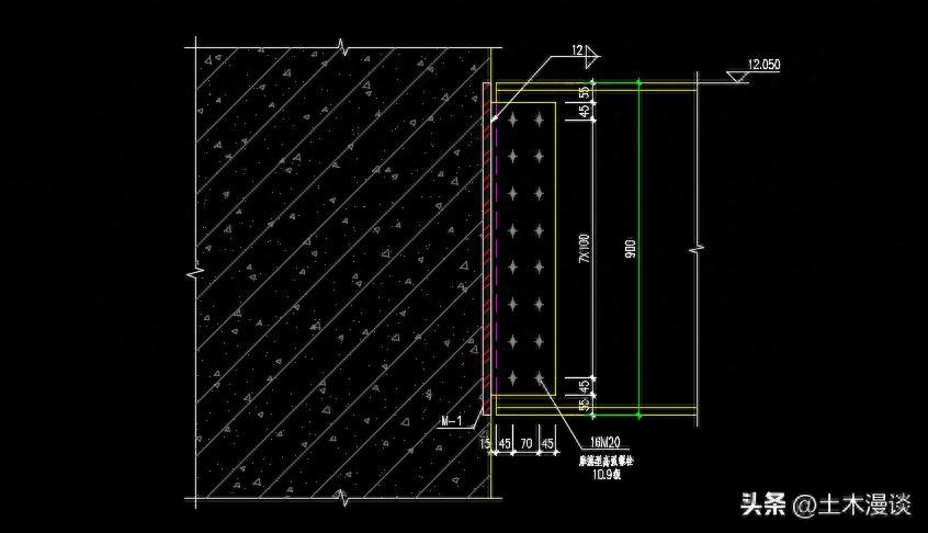
Welding deformation control ensures structural accuracy
The segmented de-welding method and anti-deformation process are used to weld the main beam to reduce the impact of heat input on structural accuracy. In one project, a laser tracker was used to monitor welding deformation in real time, so that the side curvature of the main beam was controlled within the range of L/2000. In other words, when the span was 30 meters, the side curvature did not exceed 15 mm.
After welding is completed, vibration aging treatment needs to be carried out to eliminate residual stress and prevent crack expansion. The connection parts of the end beams are fastened with high-strength bolts and combined with shear plates to improve the fatigue resistance of the nodes. This hybrid connection method makes maintenance and replacement more convenient.
Non-destructive testing ensures safety and reliability
Ultrasonic flaw detection is used to detect the quality of welds to ensure that there are no defects such as cracks in the main beam. In one project, 1.25 times the specified rated load was applied during the static load test to verify that the bridge device had no residual permanent deformation, and ultimately met the requirement of meeting national safety standards.
How is the core load-bearing structure of the bridge crane designed where high-strength bolts are connected? Torque testing must still be carried out to ensure that the pretightening force meets the standards. Just like when a certain crane was accepted, all 128 high-strength bolts were randomly inspected, and the pass rate reached 100%, ensuring the service life of the entire structure.

Regarding the design of bridge cranes, what do you think is the most outstanding advantage of high-strength bolted connections compared to all-welded structures? Feel free to share your personal opinions and ideas in the comment area, and please like and repost so that more people can see these corresponding design key points.


暂无评论内容