
Common problems in milling processing are as follows: 1. Tool wear is too fast 1
During the milling process, we encountered problems such as rapid tool wear, rough surfaces, inaccurate dimensions, and chatter marks. This not only slowed down the production progress, but also directly pushed up the processing cost. Next, combine specific data and operational details to analyze the causes and solutions to these four common problems.
Three countermeasures for excessive tool wear
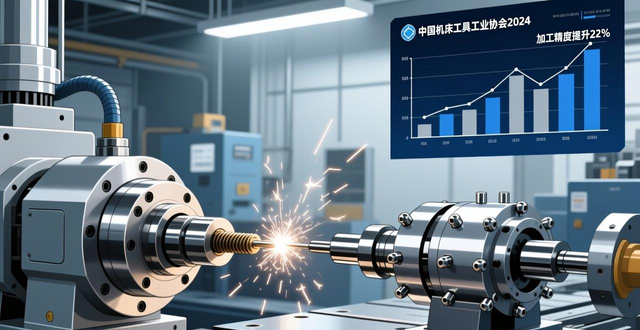
In a machining industry survey conducted in 2025, more than 60% of milling scraps were directly related to tool condition. When the cutting speed exceeds 20% of the recommended value for carbide tools, the tool temperature may rise to more than 800 degrees Celsius, thereby accelerating coating peeling and matrix softening. The operator can make a judgment by looking at the width of the wear band on the tool flank surface: when the width reaches 0.3 mm, the tool should be changed immediately.
Common problems in milling processing of different workpiece materials are as follows: 1. Tool wear is too fast 1. Corresponding tool brands need to be selected. When processing mold steel with a hardness greater than HRC45, fine-grained carbide milling cutters containing aluminum titanium nitride coating should be used. Their lifespan can be 3 to 5 times longer than that of ordinary tools. At the same time, ensure that the direction of the coolant injection is aimed at the cutting area, and the flow rate is not less than 5 liters per minute, so that the heat can be effectively taken away.
Specific operations to improve surface roughness
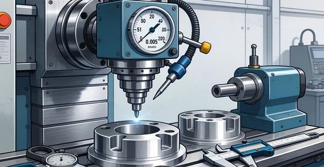
When the surface roughness value Ra exceeds 3.2 microns, the workpiece often requires secondary finishing, which will increase the working hours by more than 30%. Adjusting the feed per tooth is the key to controlling roughness: during finishing, the feed per tooth needs to be controlled in the range of 0.05 to 0.1 mm, and at the same time, a milling insert with a wiper edge must be used, which can significantly reduce the height of the tool mark.

The runout of the machine tool spindle should be controlled within 0.005 mm. Otherwise, periodic lines will be left on the surface of the workpiece. During work in the factory where the precise standard parts of the 2024 model are located, after adjusting the runout of the spindle from 0.015 mm to 0.005 mm, the surface roughness of the aluminum alloy parts dropped from Ra 1.6 microns to Ra 0.8 microns. In addition, before processing, check whether the workpiece material has segregation or hard spots. This can prevent local strain on the workpiece surface.
Systematic investigation of excessive dimensional accuracy
Workpieces with dimensional deviations exceeding 0.05 mm are prone to interference or excessive gaps during assembly. First, measure the actual diameter of the tool. A nominal 10 mm milling cutter may only be 9.94 mm after wear. If no compensation is performed during programming, the width of the milled groove will be 0.06 mm smaller. It is necessary to regularly use a laser tool setter to measure the tool length and radius, and update the wear compensation value in the CNC system.
When milling thin-walled parts, the elastic deformation caused by the cutting force is the main cause of dimensional deviation. For example, when processing an aluminum part with a wall thickness of 2 mm, if the cutting depth is 0.5 mm, the workpiece is likely to be offset by 0.03 mm. If you adopt symmetrical milling and layered processing, and ensure that the depth of each cut does not exceed 0.2 mm, and at the same time use vacuum suction cups or soft claws to increase the clamping area, you can effectively control deformation.
How to eliminate chatter and chatter
The vibration patterns on the surface of the workpiece show a wavy pattern, and the surface roughness is improved by CNC milling with uniform spacing, and its depth is in the range of 0.01 to 0.03 mm. The overhang length of the tool holder should be checked. If the ratio of the overhang length to the tool holder diameter is greater than 4 to 1, then the system rigidity will drop significantly, and chatter will easily occur. When performing deep cavity machining, it is best to use a thickened tool holder, or use a vibration-damping tool holder to control the overhang ratio within 3:1.
The combination of cutting width and cutting depth will improve the surface roughness of CNC milling , which will also affect the stability. Using a small cutting width and large cutting depth processing method is less likely to cause chatter than a large width and small cutting depth. At the same time, the workpiece must be inspected For clamping, use a torque wrench to tighten the platen bolts to the specified torque. For example, M12 bolts need to be tightened to 50 N·m, and make sure the bottom of the workpiece is completely fit and firmly padded. If the spindle bearing clearance is too large, machine tool maintenance personnel should be arranged to readjust the pretightening force.
Key points for optimization of cooling and lubrication systems
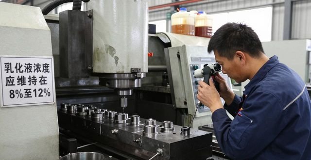
The coolant concentration at many processing sites is not tested for a long time, resulting in a decline in lubrication performance. For milling steel, the emulsion concentration should be maintained within the range of 8% to 12%. If the concentration is too low, friction and temperature will increase. If the concentration is too high, foam will easily occur. Use a refractometer to check the concentration once a week, and replenish the original solution in time.
High-pressure internal cooling milling cutters that can directly send coolant to the cutting edge can reduce the temperature of the cutting zone by about 200°C compared with external cooling. In 2025, an auto parts factory switched to a milling cutter with an internal cooling pressure of 3 MPa when processing high-temperature alloys, and the tool life was increased from 80 pieces to 150 pieces. And regularly clean the iron filings and sludge in the coolant tank to keep the filter clear.
Daily measures to maintain machine tool accuracy
After half a year of operation, the lead screw clearance of the CNC milling machine may increase to more than 0.02 mm, which will affect the positioning accuracy. Every quarter, a laser interferometer needs to be used to measure the backlash of each axis, and the compensation value must be filled in the parameters of the CNC system. The runout of the spindle nose and the tapered surface of the tool holder need to be cleaned regularly to prevent iron filings from being brought in, which will lead to eccentricity in the clamping.
For guide rail lubrication points, oiling operations must be performed at least once per shift, and guide rail oil with appropriate viscosity must be used. It is necessary to check the coupling to see if it is loose, so as to avoid relative rotation between the motor and the screw. A machine tool inspection table needs to be developed. Operators must record the temperature and vibration of the spindle every day. Once an abnormality is discovered, timely repairs must be made to prevent small problems from developing into accuracy failures.
What other embarrassing problems have you encountered during milling? Welcome to write down your examples and solutions to improve CNC milling surface roughness in the comment area, like and share it, so that more colleagues will not have to take so many unfair paths in this regard.


暂无评论内容