ブログ

  • Procurement director must read: large mining excavator seven core parameters depth comparison and avoid pit guide

    Procurement director must read: large mining excavator seven core parameters depth comparison and avoid pit guide

    主な記事

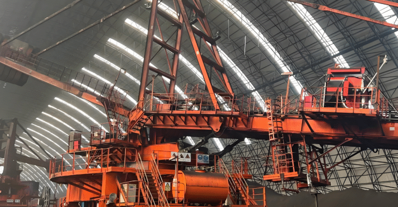
    Last week, we had dinner with Lao Zhang, the equipment minister of an open-pit coal mine in Inner Mongolia, who lamented, “Last year’s purchase ofThe 380-tonne mining excavator.The parameter table has been read for three months, but the result is still falling into the pit.” He said the “pit” is very specific: when the equipment is working at full load, the bucket rod hydraulic oil temperature is 8 ℃ higher than the competitors, resulting in every 600 hours of work in advance to replace the hydraulic oil, alone this increase in maintenance costs of 150,000 yuan per year.

    This story is not uncommon in the mining equipment procurement circle. Procurement of large mining excavators, often tens of millions of dollars of investment, the parameters of the table densely packed data, which is a marketing gimmick, which is the real performance indicators? I combine seventeen years of industry experience, for you to sort out the seven most easily misunderstood but vital parameters.
    I. The “effective power” trap behind engine power
    The “rated power” on the parameter table and the “available power” in actual operation are two different things. The procurement case of an iron ore mine in Shanxi in 2021 is very representative: they compared three excavators of the same tonnage, with a nominal power of 1,250kW for brand A, 1,200kW for brand B, and 1,180kW for brand C. According to the conventional thinking, brand A is obviously the most powerful.

    But the actual field measurements were surprising:

    Brand A power attenuation rate of 22% in mining area at 1800 metres above sea level

    Brand B is equipped with a plateau adaptive system that controls the attenuation rate to 12%

    Although the C brand has the lowest nominal power, it has more low-speed torque and is actually the most efficient in terms of loading.

    Key point: not only should you look at the standard working condition power at sea level, but also ask for the measured power curve under the altitude and temperature conditions in your mining area. Ask the supplier to provide fuel consumption and power data of the same model of equipment under similar working conditions in the previous three years, which is more useful than any brochure.

    II. The art of balancing working weight and grounding specific pressure
    “The bigger the tonnage, the better” is a common misconception. A bauxite mine in Henan had purchased a 380-tonne excavator, which got stuck in soft ore layers during the rainy season, resulting in more than three weeks of downtime each year. Later, they switched to a 360-tonne model with wider track plates, and the ground pressure was reduced from 178kPa to 152kPa, which solved the passability problem completely.

    The formula for calculating the grounding specific pressure: Operating weight ÷ (Track length × Track width × 2). This parameter is often hidden in supplier samples, but you must calculate it. Generally speaking, for mines with soft soil, it is recommended to control the grounding ratio pressure at 140-160kPa; for hard rock mines, it can be relaxed to 170-190kPa.

    Three invisible indicators of the hydraulic system
    Most purchasers focus on the obvious parameters of hydraulic pump displacement and operating pressure, but it is often the following three invisible indicators that really affect long-term reliability:

    Hydraulic Fluid Cleanliness Retention: Suppliers are required to provide NAS cleanliness rating data for hydraulic systems. A good quality system will maintain NAS 7 or less for 2000 operating hours, while a poor system will drop to NAS 9 in 600 hours. For each level of degradation, pump and valve life is reduced by approximately 301 TP3T.

    Thermal equilibrium point setting value: The optimal working temperature range of hydraulic oil is 65±5℃. A national brand through the optimisation of the radiator layout, the limit working condition oil temperature control within 72 ℃, while some brands in the ambient temperature of 35 ℃ when the oil temperature reaches 82 ℃, which is a design flaw.

    Flow Matching Accuracy: Modern large excavators use positive flow control systems that require a flow matching error of less than 51 TP3 T. You can request to see the “Compound Motion Coordination Test” data in the third party test report.

    IV. Methods for identifying the design life of structural components
    The life of structural components is a decisive factor in the economics of equipment. The practice of a large domestic copper mine is worth learning from: they require suppliers to provide three points in the bidding documents:

    Finite element analysis report of moving arm and bucket bar (focusing on stress concentration areas)

    Calculation of the L10 life of the slewing ring (should not be less than 30,000 hours)

    Chassis X-frame weld inspection standard (100% ultrasonic inspection required)

    They found that the same nominal 50-tonne bucket capacity excavator, A brand dynamic arm design life of 20,000 hours, B brand reached 28,000 hours, while the price difference is only 8%. equipment minister calculated an account: according to the cost of operating 1200 yuan per hour, this 8000 hours of the gap means that nearly ten million potential value.

    V. Environmental resilience indicators for electrical systems
    Mining environment is a severe test for the electrical system. A coal mine in Xinjiang is located in a windy and sandy area, and they have summarised a set of electrical system assessment methods:

    Protection level: IP rating of key electrical components such as controllers and sensors is required to be not less than IP67 (dustproof and waterproof), not just the whole machine protection level.

    Harness quality standards: require the use of oil-resistant, high-temperature-resistant harnesses, connectors must be gold-plated contacts. There is a simple identification method: the number of grounding points in the electrical schematic diagram is required to be viewed. High-quality design every 3-5 metres there is a grounding point, poor quality design may be more than 10 metres to have a.

    Electromagnetic compatibility: Large mining equipment intensive area with serious electromagnetic interference. Suppliers are required to provide third-party EMC test reports to ensure that the system can work normally in a strong electromagnetic field of 30V/m.

    VI. The correct way to interpret fuel consumption data
    “Fuel consumption per tonne of material is more informative than fuel consumption per hour. We have tracked the actual data of six excavators of the same class in Northeast China:

    Model Hourly fuel consumption(L/h) Actual hopper capacity(m³) Fuel consumption per tonne of material(L/t) Annual difference cost
    Brand A 185 22.5 0.041 Baseline
    Brand B 192 24.1 0.040 -$120,000
    Brand C 178 21.8 0.041 +$30,000
    It looks like the B brand has the highest hourly fuel consumption, but because of its larger bucket capacity and short operating cycle time, the actual tonne of material has the lowest fuel consumption. According to the annual working hours of 5,000 hours, but the most fuel-efficient.

    VII. Quantitative assessment of ease of maintenance
    Maintenance costs account for 40%-60% of the total lifecycle cost of the equipment. it is recommended that a “simulated maintenance exercise” be conducted prior to purchase:

    Routine maintenance point accessibility: Suppliers’ representatives are asked to demonstrate on-site routine operations such as changing air filters, checking hydraulic oil levels, etc., and to record the time and types of tools required.

    Overhaul cycle data: Ask for the first overhaul time for similar equipment under similar operating conditions. Quality equipment should have its first engine overhaul at 20,000-25,000 hours, while poor quality equipment may need it at 15,000 hours.

    Intelligent degree of diagnostic system: modern equipment should have fault prediction function. For example, a brand of excavators can be based on the trend of hydraulic oil contamination degree, 200 hours in advance warning filter replacement needs.

    Final recommendation: Form a 5-7 person technical evaluation team, including first-line personnel such as machine shop supervisors, capable operators, and electrical engineers. Let them participate in equipment inspection and parameter review, often can find the practical details that engineers ignore. Parameter table is dead, the equipment is alive, the real good equipment is those in your particular mine “with the smooth, repair and worry, calculate the money” equipment.

  • 究極の機械加工ガイド:原理・プロセスから最新アプリケーションまで、精密加工の真髄を一冊で読み解く

    加工It is the cornerstone technology of modern manufacturing industry. This article comprehensively analyses the core principles, mainstream processes, technological evolution and industry applications of machining, providing you with a professional framework and decision-making guide for choosing machining services.

    body of the article
    Introduction: When Design Meets Solid – How Machining Turns Ideas Into Reality
    Imagine: a medical device engineer designing a new orthopaedic implant with complex 3D surfaces and micron-level precision requirements that can only be achieved through machining; a self-driving startup team needing special customised sensor mounts, in small batches, with high precision and rapid iteration – this is at the heart of the modern machining services scenario.

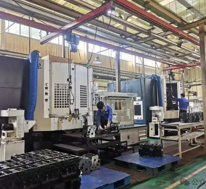
    Machining, or machining, is a manufacturing process in which raw materials (metals, plastics, composites, etc.) are accurately machined into parts of the desired shape, size, and surface quality by removing material using machine tools and cutting tools. Representing subtractive manufacturing, it remains the preferred production technology for high-precision, high-strength, and high-reliability parts. Whether you are looking for machining services or wish to gain a deeper understanding of this fundamental industrial technology, this article will provide you with a panoramic and professional interpretation.图片[1]-机加工终极指南:从原理、工艺到现代应用,一文读懂精密制造的核心-大连富泓机械有限公司

    Part I: Understanding machining – it’s not just about “cutting”!
    1.1 The core concept of machining: the controlled “art of subtraction”
    Unlike 3D printing (additive manufacturing), machining achieves modelling by physically removing material. At the heart of this process lies extreme control over three elements:

    Motion control: precise relative motion between tool and workpiece

    Material removal: removal of excess material by shearing, tearing or grinding

    Accuracy management: real-time assurance that size, shape and surface quality meet design requirements

    1.2 Three Pillar Elements of Modern Machining
    Elements Traditional model Modern advanced model
    Equipment/Machine Tools Manual General Purpose Machines CNC Machines, Multi-Axis Machining Centres, Turning and Milling Centres
    Cutting tools Standard high-speed steel cutting tools Carbide/ceramic/ultra-hard coated cutting tools, custom moulded cutting tools
    Controls & Programming Operator Experience & Handwheels CAD/CAM Software, Digital Twin, AI Process Optimisation
    Part II: A Complete Overview of Mainstream Machining Processes – From the Basics to the Cutting Edge
    Different part characteristics require different machining methods. The following is a classification of the most significant machining processes used in modern manufacturing:

    2.1 Basic classification: by main mode of movement
    1. Turning

    Principle: Workpiece rotation, radial or axial feed of a fixed tool.

    Expertise: cylindrical, conical, threaded and other rotary features

    Typical equipment: CNC lathes, turning centres

    Accuracy range: IT6-IT8 grade, Ra 0.4-1.6μm

    2. Milling

    Principle: the tool rotates and the workpiece moves in the XYZ direction

    Expertise: planes, slots, gears, complex 3D surfaces

    Typical equipment: Vertical/horizontal machining centres, gantry milling machines

    Modern evolution: five-axis linkage for machining complex aerostructural parts in one go

    3. Drilling & Boring

    Drilling: creation of new holes in solid material with relatively low accuracy

    Boring: Enlargement and finishing of existing bores to very high accuracy and coaxiality

    Key technologies: deep hole drilling, gun drilling, co-ordinate boring machines

    4. Grinding

    Principle: Microscopic cutting with a high-speed rotating grinding wheel

    Unique value: Hardened hard materials can be machined for highest surface quality

    Applications: precision moulds, spindles, guideways, tool sharpening

    2.2 Speciality machining: non-traditional methods for solving special problems
    5. Electrical Discharge Machining (EDM)

    Includes wire erosion (WEDM) and moulding EDM.

    Advantage: any conductive material can be processed, not limited by material hardness.

    Typical applications: precision moulds, microfabricated holes, carbide tools

    6. Laser processing

    Principle: High-energy laser beam melts and vaporises material

    Features: non-contact, small heat affected zone, suitable for complex contour cutting

    Modern development: laser additive and subtractive composite manufacturing becomes the cutting-edge direction

    Part Three:The heart of modern machining-CNC and Digital Transformation
    The soul of modern machining is computer numerical control (CNC) technology. This change has revolutionised the game in the industry:

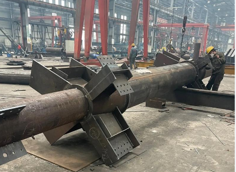
    3.1 Fundamental advantages offered by CNC图片[2]-机加工终极指南:从原理、工艺到现代应用,一文读懂精密制造的核心-大连富泓机械有限公司
    Consistency: Human error is eliminated, ensuring that the 1st piece is identical to the 1000th piece.

    Complexity: complex surfaces and structures that cannot be machined by conventional methods can be easily realised

    Flexibility: switching between different parts through programme changes, suitable for small quantities and many varieties.

    Integration: Seamless integration with CAD/CAM/CAPP/PLM systems for a fully digital manufacturing process

    3.2 Complete digitisation process from drawing to part
    3D modelling: engineers create part models using SolidWorks, UG/NX, etc.

    Process planning: Determination of machining sequences, clamping programmes, tool paths

    CAM programming: the software automatically generates G-codes recognisable by the machine tool.

    Simulation verification: checking collisions and optimising cutting parameters in a virtual environment

    Machine tool machining: CNC system for precise execution of programme instructions

    On-line inspection: automatic probe measurement for closed-loop quality control

    Part IV: Key technical indicators and quality control of machining
    The core indicators for evaluating machining capacity constitute a professional framework for the selection of suppliers:

    4.1 The precision pyramid: understanding the different levels of precision required
    Accuracy Levels Typical Metrics Application Scenarios
    General accuracy ±0.05mm General structural parts, housings, brackets
    Precision machining ±0.01mm Hydraulic components, transmission parts, precision moulds
    Ultra-precision machining ±0.002mm Optical components, semiconductor fixtures, medical devices
    Nanoscale machining <0.0001mm Aerospace gyroscopes, chip manufacturing equipment
    4.2 Multi-dimensional evaluation of surface quality
    Roughness (Ra, Rz): from Ra 12.5 (roughing) to Ra 0.1 (mirror effect)

    Surface texture: turned circular grain vs. ground cross grain

    Surface properties: work hardening, residual stress, corrosion resistance

    4.3 Material adaptation: from aluminium to high-temperature alloys
    A good machining service provider should be able to handle it:

    Lightweight materials: aluminium alloys, magnesium alloys (attention needs to be paid to chip removal and deformation control)

    Structural steel: 45# steel, 40Cr, mould steel (heat treatment condition to be considered)

    Stainless steel: 304, 316, 17-4PH (special tools and parameters required)

    Difficult-to-machine materials: titanium alloys, high-temperature alloys, cemented carbides (reflecting real technical strength)

    Part V: How to Choose a Professional Machining Service Provider – 7 Key Evaluation Dimensions
    When you need to find a machining partner, it is recommended to systematically evaluate the following dimensions:

    5.1 Equipment capacity assessment
    Machine type and brand: German and Japanese high-end machines usually represent higher stability and precision reserves.

    The degree of newness of the equipment: regularly updated equipment to ensure that the processing capacity is not outdated

    Key features: linear motors, torque motors, thermal compensation system and other advanced features

    5.2 Technical team and experience
    Programmer experience: ability to plan processes for complex parts

    Operator skills: experience with special materials and processes

    Quality Engineer qualification: depth of understanding of measurement techniques and quality systems

    5.3 Quality Assurance System
    Inspection equipment: Coordinate measuring machine, roundness meter, roughness meter, etc.

    Process control: rigour of execution of first article inspection, inspection, final confirmation

    Certifications: ISO 9001, AS 9100 (aerospace), ISO 13485 (medical devices), etc.

    5.4 Responsiveness and Collaboration
    Communication mechanisms: responsiveness and professionalism of technical clarifications

    Problem solving: the ability to analyse and improve when encountering machining difficulties

    Flexibility: responsiveness to design changes and urgent needs

    Part VI: Future Trends and Innovative Directions in Machining
    6.1 Intelligent Upgrade
    Adaptive processing: real-time parameter adjustment based on vibration and acoustic emission signals

    Predictive maintenance: Predicting tool life and equipment failure through data analysis

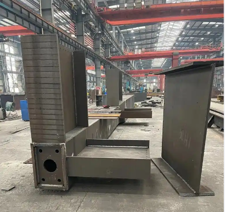
    Process optimisation AI: machine learning from historical data to recommend optimal cutting parameters图片[3]-机加工终极指南:从原理、工艺到现代应用,一文读懂精密制造的核心-大连富泓机械有限公司

    6.2 Composite development
    Additive-Subtractive Composites: 3D Printing Near-Net Shaping + CNC Finishing

    Multi-functional composite machine tools: mill-turn, mill-grind, and laser material additive and subtractive machines

    In-line measurement integration: real-time measurement and compensation during machining processes

    6.3 Sustainable Progress
    Green cutting: micro lubrication (MQL), low temperature cooling and other environmentally friendly technologies

    Energy efficiency: optimising processing parameters to reduce energy consumption

    Material utilisation: improved material utilisation through optimised nesting and process chains

    Conclusion: Machining – the eternal cornerstone of precision manufacturing and the frontier of innovation
    Machining is far more than simply “cutting metal”; it is a complex systems engineering that integrates materials science, machine dynamics, computer science and precision measurement technology. In the rapid development of additive manufacturing, machining has not been replaced, but through the integration of new technologies, continue to expand the boundaries of its own capabilities.

    Whether you are a design engineer needing to turn ideas into reality, or a manufacturing company looking to optimise your supply chain, understanding the core principles of machining, process selection and quality control points will help you make better decisions. Truly professional machining services provide more than just “build-to-print” execution; they provide a total solution from design for manufacturability to process optimisation to quality assurance.

    Recommendations for next steps:
    If you are looking for machining solutions for a specific project, it is recommended to prepare in the following ways:

    Organise complete requirements: including 3D models, 2D drawings, material requirements, accuracy levels and acceptance criteria

    Define critical features: identify the most critical dimensions and functional surfaces in the part

    Considering the full life cycle: including surface treatment, cleaning packaging and other post-treatment needs

    Request for process options: request potential suppliers to provide initial process planning and risk assessment

  • 機械加工プロセス標準を解説:ISO、GB、ASME、グローバルな製造の一貫性を確保するには?

    機械加工プロセス標準規格これは品質の世界共通言語です。この記事では、ISO、GB、ASME、その他の中核となる標準システムが、部品の世界的な互換性と信頼性を確保するために、寸法公差、形状公差、位置公差、表面仕上げをどのように規定しているかについて説明します。

    機械加工 プロセス標準:グローバル化した製造業の礎石であり世界共通語

    はじめに1つの部品を世界中の複数の場所で生産する」というシナリオから、規格の重要性を紹介する。規格がなければ、現代の大規模な共同生産は成り立たない。

    I.なぜ職人技の基準が重要なのか?

    (互換性、品質の一貫性、コミュニケーション効率、貿易円滑化)

    II.コア加工プロセス標準システムの紹介

    1.国際規格:ISOシステム(例:ISO2768一般公差)

    2.中国の国家規格:GBシステム(ISO対応)

    3.米国規格:ASME Y14.5 等。

    4.業界および社内基準

    III.基準の対象となる中核的な内容領域

    1.寸法公差とはめあいのシステム(ベースホール・システム/ベースシャフト・システム)

    2.幾何公差(形状公差と位置公差)記号と意味クイックチェック

    3.表面粗さの記号と評価パラメータ(Ra、Rz)

    4.図面のラベリングに関する規定

    第四に、着地処理の基準を見るためのチャートである。

    (フローチャート:顧客図面ラベリング標準→エンジニアが標準を解釈→プログラミングとプロセス設定→オペレーターが実行→QCが標準に従って検査)。

    結論とCTA規格はフレームワークであり、各注文に特化した詳細な加工工程要件に変換する必要がある。具体的な要求事項の作成方法については、次回の記事をお読みください(記事4へのリンク)。

    よくある質問

    「公差が図面に記載されていない場合はどうすればよいですか?" (A: 通常はISO 2768-mKまたは同様の一般公差規格に従います)

    "アメリカンスタンダードとナショナルスタンダードの図面、図面を読むときの最大の違いは何ですか?"(答え:透視投影法が違う:アメリカンスタンダードは第3コーナー投影が一般的、ナショナルスタンダードは第1コーナー投影、図面を見る時にまず確認する必要がある)

  • 加工方法と加工の特徴、主流7工程と選択ガイドとは?

    探検加工世界!この記事では、旋削、フライス、ドリル、ボーリング、研削、ワイヤーカット、レーザー加工7主流の方法の詳細な分析、その加工特性、精度、適用される材料の詳細な比較は、プロジェクトに最適なプロセスを選択するのに役立ちます。

    加工方法のパノラマ:特徴の詳細分析と実用的な選択

    はじめに:「機械工場を理解することが第一歩であり、そのコア技術の核心に触れることが、効果的なコミュニケーションを図る唯一の方法である。部品の特性が違えば、加工方法も異なる。"

    I.分類の基本:回転性対非回転性、接触性対非接触性

    II.7つのコア加工モードの詳細(各モードに1つのH3)

    1.回転 - ボディパーツの回転王

    特徴ワーク回転、工具送り外形、内径、端面、ねじの専門家。

    精度と表面粗さの範囲。

    (核心提示:その特徴と用途を明確に説明すること)

    2.フライス加工 - 複雑な輪郭や平面に対応。

    特徴工具回転、ワーク送り平面、溝、歯車、3Dサーフェスに精通。

    (縦型・横型フライス盤、CNCマシニングセンター)

    3.ドリリングとボーリング - 穴あけスペシャリスト

    穴あけ:比較的精度の低い新しい穴を加工すること。

    ボーリング:既存の穴を高精度に拡大し、仕上げること。

    4.研削 - 究極の精度と仕上げ

    特徴砥石によるマイクロ切削で、焼入れ後の硬質材料の仕上げに使用される。

    5.ワイヤーエクスキジョン(WEDM)-硬い素材や複雑な金型用

    特徴電気火花放電を利用した非接触式。導電性の超硬質材料を切削力なしで加工できる。

    6.レーザー切断 - 効率的で正確なシートメタル切断ソリューション

    特徴:非接触、熱処理。速度が速く、切断面の品質が良く、薄板に適している。

    III.プロセスの比較と選択

    (プロセス名、主要動作、典型的な精度、表面品質、特殊機能、制限事項をリストアップした比較表を作成する)

    IV.現代のトレンド複合処理とインテリジェンス

    (複合旋盤と多軸マシニングセンタの利点を簡単に説明しなさい)

    結論とCTAこれらの工程の特徴をマスターすることは、高品質の機械加工を理解するための前提条件である。真の品質保証は、加工工程の厳格な基準と仕様から生まれる(記事IV/V/VIへのリンク)。

    よくある質問

    "CNC加工はどの方法に該当しますか?"(A:CNCは制御方法の一つであり、特定の工程ではありません。旋盤(CNC旋盤)、フライス盤(マシニングセンター)、研削盤などを制御し、上記の加工方法の多くで自動化・高精度化を実現することができます)

    "アルミ部品とスチール部品の加工方法選択の違いは何ですか?"(A:基本的な工程は同じですが、切削パラメータ、工具材料、クーラントの選択に大きな違いがあります)

  • 機械工場の仕事とは?図面から部品まで、ものづくりの核となるサービスについての記事

    ワンダーマシンショップ具体的にどのようなサービスを提供しているのでしょうか?この記事では、旋盤加工、フライス加工、穴あけ加工、研削加工など、機械加工工場の中核業務について詳しく説明します。設計図面を高精度の金属/プラスチック部品に変える方法は、信頼できるサプライヤーを探すための出発点です。

    本文の概要(-H3構造)。

    機械加工とは?設計図から物理的な現実まで、お客様の製品を実現します。

    はじめに一般的な工業製品(自動車部品、医療機器、ドローンのフレームなど)を例にとると、それらの基幹部品には機械加工が不可欠であることが指摘されており、機械加工工場が現代製造業の「要」としての役割を担っている。

    I.機械工場の本質:減法製造のスペシャリスト

    減法的製造」の概念を説明し、3Dプリンティング(加法的製造)と比較する。

    II.機械工場の中核的サービスプロセス

    1.図面分析と工程計画

    2.原材料(棒、板、鋳物、鍛造品)の準備

    3.コア・プロセス製造(旋盤加工、フライス加工、ドリル加工などの簡単なリスト。)

    4.品質検査と再処理

    5.完成品の納品

    III.機械加工工場がサービスを提供する一般的な産業と製品タイプ

    (アイコンやリストで表示:航空宇宙、自動車製造、医療機器、電子機器、金型・ダイフィクスチャーなど)

    第四に、資格のある機械工場をどう選ぶか。

    (考慮すべき主なポイント:設備能力、工程経験、品質システム、納期管理、そして「標準」に関する後続記事の舞台設定)

    結論とCTA機械加工工場は、製品を軌道に乗せるための重要なパートナーです。私たちがどのような高度な機械加工方法を駆使しているのか、またそのユニークな特徴については、技術的な詳細をご覧ください(記事2へリンク)。

    よくある質問

    「機械加工と板金加工の違いを教えてください:機械加工は主に立体のブロックを立体的に切削するもので、板金は主に薄い板を切削、曲げなどの成形加工するものです)

    "小ロットの試作部品を機械工場に依頼できますか?"(A:はい、多くの工場がラピッドプロトタイピングサービスを提供しており、CNC機械加工は少量の高精度プロトタイプに最適です)

    "機械工場からの見積もりの根拠は?"(回答主に材料費、加工工数(プログラミングと機械加工時間)、工程の複雑さ、後加工の必要性などです)

  • What equipment do you need to start a riveting factory?2025 essential equipment investment list (with shopping advice)

    scheduled openingRivet Welding Processing PlantThis article provides you with a list of all the equipment you need from small workshops to medium-sized factories. This article provides you with a list of all the equipment you need from a small workshop to a medium-sized factory, including material handling, moulding, riveting, welding and auxiliary equipment, as well as key points for purchasing, which will help you to plan your investment wisely.


    The ultimate guide to riveting plant equipment: a checklist of must-haves for investing in a plant

    Introduction: Professional and systematic equipment planning solutions for entrepreneurs and factory managers.

    I. Sheet Metal Unloading and Forming Equipment Area

    1.1 Cutting equipment: plate shears, CNC flame/plasma cutting machines, laser cutting machines (selected according to size)

    1.2 Forming equipment: bending machines, plate rolling machines, punching machines

    II. Core riveting and assembly equipment area

    2.1 Drilling equipment: bench drills, rocker arm drills, magnetic drills (according to the size of the workpiece)

    2.2 Riveting equipment: manual/pneumatic/electrical riveting guns, riveting presses, pneumatic riveting hammers, ring groove rivet guns

    2.3 Assembly and clamping: C-clamp, F-clamp, various jigs, assembly platforms

    III. Welding and reprocessing equipment area (“riveting” usually includes welding)

    3.1 Welding equipment: welding machine (electric arc welding, gas shielded welding), welding consumables

    3.2 Post-treatment equipment: Angle grinders, sandblasting machines, spraying equipment

    IV. Auxiliary and safety equipment area

    (lifting equipment, dust removal systems, personal protective equipment PPE, etc.)

    V. Equipment Investment and Layout Recommendations

    Option A: Core equipment list for a small repair workshop ($100,000 – $200,000 budget)

    Option B: Core equipment list for a medium-sized structural fabrication plant ($500,000 – $1 million budget)

    Strong CTA: [Get a detailed list of equipment models and quotes] “The above is a category overview only. If you need detailed equipment brand, model recommendation and budget planning for a specific processing type (e.g. steel structure, container, ventilation duct), please leave your contact information or needs and our experts will provide you with a free consultation.”

    よくある質問

    “What are the three most preferred pieces of equipment to buy to start a small riveting workshop?” (Answer: Cutting equipment (e.g. plasma cutter), drilling equipment (bench/magnetic drill), and riveting equipment (pneumatic rivet gun).)

    “What’s the difference between pressure riveting machine and pull rivet gun, which one is more efficient?” (A: Pressure riveting machine is used for solid rivets with holes in advance, requires double-sided operation, extremely high strength, suitable for batch; pull rivet gun is used for core-pulling rivets, single-sided operation, flexible, suitable for multiple scenarios. Pressure riveter is more efficient in batch production.)

  • リベット溶接の操作方法とは?すべての技術的特徴を1つの表で簡単に比較

    クイック検索リベット溶接のすべての操作方法!我々は、ホット・リベット、コールド・リベット、プル・リベット技術の定義、ツール、長所、適用場面を明確な比較表でリストアップし、迅速な決断を助けます。

    图片[1]-铆焊的操作方法有哪些?一张表格快速对比所有技术特点-大连富泓机械有限公司一目でわかるリベット溶接の全作業とクイック・リファレンス・ガイド

    はじめに:本題に入り、簡単なリファレンスを提供する。

    リベット溶接作業方法概要表

    方法名、必要な主な道具、操作の簡単な説明、接続の強さ、利点、欠点、典型的な用途を列記した比較表を作成する。

    (対象:手動ホットリベット、空気圧ハンマーリベット、圧縮リベット、プルリベット、コアリベット、リング溝リベット)

    ニーズに合った方法を素早く見つける

    シナリオ1:「片側で操作する必要がある」→プルリベット、芯打ちリベットにお勧め。

    シナリオ2:「最大限の強度を求めている」→ホットリベット、リング溝リベットを推奨。

    シナリオ3:「私は工具が限られている個人的なDIYerだ」→手作業によるリベット引きを推奨する。

    拡大読書:各手法の詳細な手順

    (ここで簡単に説明し、記事1の詳細な章と記事2の対応するビデオへの内部リンクを多用している)


    "表にあるものよりも進んだリベット接合方法がありますか?"(A:はい、例えばリベットレス接合、セルフ・ピアス・リベット接合等、主に自動化された生産ラインで使用される)

    "どの方法が最もコストが低いか?" (A:最初の工具投入とリベット・コストは、通常、手動のリベット打ちでは比較的低い)

  • マスタリーへの道:実践的な問題を解決するために必見の10のテクニックビデオ解説

    Say goodbye to rivets that don’t hold or look good! This article is an in-depth solution to the challenges of riveting eccentricity, deformation, sealing, and joining dissimilar materials through advanced technique video explanations to enhance your craftsmanship.

    Advanced Rivet Welding TechniquesVideo presentation: From “know how” to “do it right”

    Introduction: For users who have mastered the basics but are having trouble with complex scenarios.

    Tip 1: How to achieve “invisible riveting”? (Perfect installation of countersunk head rivets)

    Video + lecture: countersinking (chamfering) techniques and riveting force control.

    Tip 2: A great trick for riveting in tight spaces

    Video + explanation: using a corner rivet gun or special rivets.

    Tip 3: Riveting sequence and support method to prevent deformation of thin plates

    Video + explanation: the sequence of riveting from the centre to the perimeter, staggered.

    Tip 4: Achieve a watertight/airtight riveted joint (use closed type rivets with sealant)

    Video + Explanation.

    Tip 5: Considerations for riveting dissimilar materials (e.g. aluminium to steel)

    Video + lecture: anti-electrochemical corrosion treatment.

    These advanced techniques can dramatically improve the quality of your products. If you’re planning a fabrication shop, you can’t do these jobs efficiently and with high quality without specialised equipment. Check out our ultimate list of What Equipment Do You Need in a Rivet Welding Plant (link to article six).


    “Why is there a gap in the workpiece after riveting?” (A: It may not be clamped securely or the rivet may not be of sufficient length to produce sufficient clamping force.)

    “How do I remove a riveted rivet?” (A: Video demonstrating the use of a drill to drill out the centre of a rivet.)

  • Zero Basic Riveting Techniques Video Tutorial: Hands on with your first professional rivets

    rivet weldingA must-see for newbies! This detailed video tutorial starts from scratch and teaches you to recognise the tools, choose the materials and complete your first solid and beautiful riveted piece step by step. Start learning immediately!

    Zero-Basic Rivet Welding Video Tutorial: Your First Lesson

    Introduction: Aimed at complete novices, this tutorial promises a “0 to 1” breakthrough.

    Chapter 1: Know your “arsenal” – riveting welding common tool introduction

    (Pictures showing hand drills, rivet guns, hammers, top irons, etc. and explaining what they do)

    Chapter 2: Choosing the Right “Tie” – A Guide to Rivet Type and Size Selection

    (Demonstrate solid rivets, blind rivets, open end/closed end rivets and explain the application scenarios)

    Chapter 3: Best Practices for Beginners – Single Sheet Steel Pull Rivet Project

    Video embedded: “Making a Simple Metal Hanger”

    Step-by-step illustrations (synchronised with the video).

    Item 1: Measuring and scribing.

    Project 2: Drilling techniques (how to prevent the drill bit from slipping).

    Item 3: Deburring (importance emphasised).

    Project 4: Clamping and Riveting (hands-on).

    Item 5: Final inspection and finishing.

    Chapter 4: Post-Course Exercises and Self-Checklist

    Congratulations on completing lesson one! To learn about the several ways riveting can be done and where they are each used, read our technical guide (link to article one).


    “What is the best material to use for practice?” (Answer: Aluminium or mild steel plates 2-3 mm thick are recommended, which are low cost and easy to work with.)

    “How do I choose a rivet gun?” (Answer: for occasional home use, go with a single-handle model; for frequent use, go with a two-handle, labour-saving model; check out our equipment list article for brand suggestions.)

  • HD Hands-on] Rivet Welding Methods Video: From Tool Preparation to Complete Riveting

    Intuitive learning through high-definition videorivet weldingThis page brings together the complete process video of the core operations of riveting and hot riveting! This page brings together the complete process video of the core operation methods of pulling rivets, hot rivets, etc., with key steps of text interpretation, the novice can also easily understand.

    图片[1]-【高清实操】铆焊的操作方法视频大全:从工具准备到完成铆接-大连富泓机械有限公司
    Video on how to do rivet welding (with step-by-step instructions)

    “A hundred times over, watching videos is the fastest way to learn a hands-on process like riveting and welding. We have integrated HD videos of key operations for you.”

    Before you watch: safety precautions and tool checks

    (Pictures showing helmets, goggles, gloves, and a list of tools)

    Video 1: Pull Rivet (Blind Riveting) Standard Operating Methods

    Embed video (or place video thumbnails, link to YouTube/B site, etc.)

    Video Highlights Text Commentary.

    Step 1: Select rivet size and drill bit.

    Step 2: Align the workpiece and drill the holes.

    Step 3: Insert rivets and position rivet gun.

    Step 4: Pull gun handle evenly until rivet breaks off.

    Step 5: Check that the rivets are fully formed.

    Video 2: Demonstration of the traditional process of hot riveting (teamwork)

    Embedded video

    Explanation: Emphasis is placed on heating temperature control, transfer and riveting.

    Video 3: Ring Groove Rivet Power Tool Installation Demonstration

    Embedded video

    Text description: Demonstrates the efficient industrialised installation process.

    Video collection of common operational errors (cautionary tale)

    (A short demonstration of failures caused by oversized holes and uncomfortable rivet lengths)

    CTA: Want to advance to mastery after watching basic operations? Take the next step and learn the Rivet Welding Techniques Video Explained (link to article four) for the secrets to making your work more professional.


    “Why is my rivet not riveted tight?” (Answer: Possible causes: Hole diameter too large, insufficient length of the nail shank, head not selected correctly.)

    “Where can I buy the tools used in these videos?” (A: A detailed list of tools and equipment is included in our next article, “What All Equipment is Needed in a Rivet Welding Plant.”)