
Precision measurement method
The precision of parts is just like the reference mark of human health. Once it deviates from the standard, the entire machine will age prematurely or even be scrapped directly. Mastering these 13 core measurement methods for large-scale parts processing measurement technology can make your machined workpieces last for several more years.
The most direct way to measure straightness is to use the end-to-end connection method.
When measuring straightness errors, the most commonly used method is to connect the beginning and end of the actual measured line to create a straight line. This straight line is used as the ideal reference baseline, and then the distances from each point on the actual contour line to this baseline are measured, and the maximum deviation value is selected as the error. This method is simple and easy to operate and can be completed in an ordinary conventional workshop. It is especially suitable for rapid detection of the straightness of the busbar of shaft parts.
For the straightness requirements of precision parts, higher-precision measuring equipment must be used. For example, with the help of a laser interferometer and a straightness accessory, micron-level deviations can be detected, and the measurement results can automatically form an error curve. There is a domestic machine tool factory. The equipment introduced in 2024 has improved its guide rail straightness detection accuracy by 40%.
Flatness detection is inseparable from the table method and level
The most basic method for detecting flatness in the workshop is the metering method. This is a large-scale parts processing measurement technology where the workpiece is placed on a flat plate. A dial indicator is used to move on the plane and the maximum change of the needle is read. During operation, be careful that the movement path of the meter must cover the entire plane and do not miss the edge area. In 2025, a mechanical processing factory used this method to discover that the flatness of a batch of valve body end faces was out of order, which promptly prevented assembly leakage accidents.
The level measurement method is more practical for large flat surfaces, such as machine tool workbenches. Move the level at a certain distance, record the reading changes at each position, and calculate the error value of the entire plane. This method does not require large-scale testing equipment, is low-cost, and is flexible to operate. Last year, a precision machinery company in Suzhou used a level to measure the distortion of a 4-meter-long casting platform.
![图片[1]-Precision Measurement Method-Dalian Fuhong Machinery Co., Ltd](/wp-content/uploads/2026/03/1773505208308_0.png)
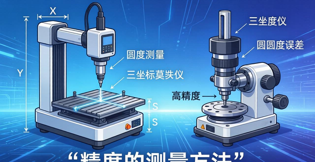
Roundness measurement: CMM and roundness meter each have their own merits
The three-dimensional coordinate measuring machine with the function of measuring roundness is a popular device for measuring roundness. Multiple sections are selected on the cylindrical surface to be measured, and a large number of points are collected for each section. The least square circle or the minimum circumscribed circle is calculated with the help of software, and then a precise measurement method of roundness error accuracy is obtained. The advantage of this method is that it can measure other geometric tolerances at the same time, and is suitable for complex parts with multi-size composite inspection.
A high-precision equipment specifically used to measure roundness is a roundness meter. It uses a high-precision rotary shaft to drive the sensor to rotate to record the radial change of the measured contour and directly draw an error graph. A well-known German auto parts supplier stipulates that the roundness of its crankshaft must be detected using a roundness meter. The measurement accuracy can reach the 0.1 micron level, thereby ensuring the smoothness and life of the engine during operation.
Cylindricity testing reflects the overall quality of parts
The comprehensive index for evaluating the shape accuracy of cylindrical surfaces is cylindricity, which covers various errors such as roundness, straightness, and parallelism of prime lines. The three-dimensional coordinate measuring machine can calculate the actual contour of an ideal cylindrical surface by scanning the entire cylindrical surface, and then obtain the cylindricity error value. This method is particularly suitable for parts such as hydraulic cylinders and precision spindles that have high requirements for sealing and matching accuracy.
In the case of small coaxiality errors, the cylindricity can be inspected by replacing the cylindricity with full radial runout. Place the part on a V-shaped block to support it. When it rotates once, move the dial indicator along the axis and read the value of the maximum runout of the needle. Although this method is not strictly cylindricity, it can quickly detect problems that may arise during the processing. A precision machining factory in Dongguan uses this method to conduct random inspections of hundreds of motor shafts every day, and its efficiency is three times higher than that of three-dimensional coordinates.
Comparing line and surface contours with templates is more intuitive
The use of large-scale parts processing and measurement technology using profiling measuring devices is the most direct method of measuring contours. Fit the processed contour template to the measured contour, and judge the error by observing the size of the light gap between the two. If the light gap is uniform and within the specified range, it indicates that the contour is qualified. This method is particularly practical in mold cavity inspection, and the master craftsman can see where it needs to be polished at a glance.
When faced with complex curved surface contours, the three-dimensional coordinate measuring machine shows a more prominent advantage. After programming it, the probe will move according to the theoretical contour trajectory, and then the actual position of each point can be automatically recorded, and then the computer can successfully calculate the error with the help of automatic comparison. In the vast field of aerospace, key components such as blades and propellers must adopt this digital inspection method, and the inspection report will be used as a necessary certificate for the product to be approved for leaving the factory.
![图片[2]-Precision Measurement Method-Dalian Fuhong Machinery Co., Ltd](/wp-content/uploads/2026/03/1773505208308_1.png)
Parallelism and perpendicularity are the basis for assembly
Usually when measuring parallelism, the datum surface of the workpiece is placed on a precision flat plate, a dial indicator is used to move on the measured surface, the difference between the maximum value and the minimum value is read, and then the conversion is performed based on the actual length of the workpiece to obtain the final parallelism error. During the measurement, it is necessary to ensure that the contact surface between the flat plate and the workpiece is clean and free of burrs, otherwise the measured data is completely unreliable. In 2024, an equipment factory reworked a batch of machine bases because of this!
Verticality testing is often carried out using a square ruler combined with a feeler gauge. When placing the square ruler, one side of the square ruler should be tightly attached to the datum plane and the other side should be close to the surface to be measured. Then use the feeler gauge to check the size of the gap between them. This method is suitable for making quick judgments on site, for example, checking the verticality of the machine tool column and the workbench. For precision parts, the datum must be leveled first, and then the straightness of the two surfaces can be measured with a level, and then the verticality error can be obtained through calculation. The accuracy can be as high as 0.01mm/m.
Position and runout errors are related to fit performance
What will directly affect the assembly and smooth operation is the coaxiality error. For barrel-shaped workpieces, directly use a caliper to measure the wall thickness uniformity and take the maximum value of the thickness difference at each point. This method is simple and crude but effective. Many gearbox factories use this method to screen unqualified bearing seat blanks, which can save hundreds of thousands of yuan in processing costs every year.
To detect the runout error, you need to equip a tip, a spindle or a V-shaped block. After the part is supported and rotated once, the maximum change indicated by the dial indicator is the radial runout error. The tip hole and supporting surface must be cleaned before measurement. Even a grain of iron filings can lead to misjudgment. In 2025, a CNC machine tool factory did not pay attention to this detail and treated the qualified spindle as scrap, resulting in a loss of more than 20,000 yuan.
When you usually test the accuracy of parts, which method is most commonly used? Have you ever encountered assembly problems due to measurement errors? Welcome to share your experience in the comment area and give it a like so that more peers can see these practical detection techniques.


暂无评论内容