
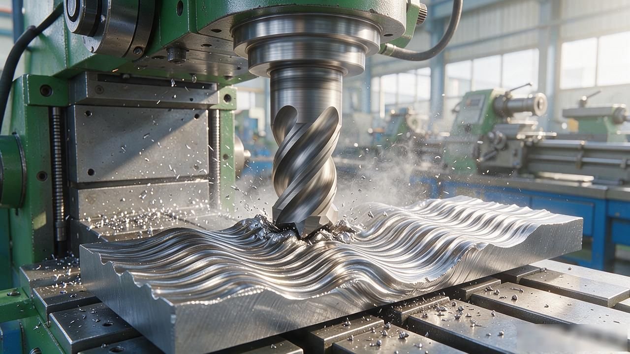
Precision in boring processing: How to perform plane processing on a coordinate boring machine
The plane formed by the precision milling process of the jig boring machine can usually achieve a surface roughness of less than 0.8 microns, and can control the position accuracy within 0.01 mm. However, under the actual operating conditions of many boring workers, the accuracy index obtained from processing often cannot meet the required standards, and there will always be a certain degree of gap.
The main reasons for such situations are often rooted in several key details that are easily overlooked by operators. For these details, they will be explained and elaborated one by one and clearly.
Control of milling dosage and allowance
When using a disc milling cutter to process a relatively large plane, the general milling allowance should be set between 1 and 3 mm. If it exceeds this range, the boring processing accuracy guarantee method and the precision of boring processing are performed on the coordinate boring machine. Because the machine tool will produce thermal deformation problems, the smoothness and accuracy of the plane will directly lower the standard.
Therefore, when selecting the milling amount, you must choose smaller values. This is a strict rule that the coordinate boring machine must abide by when performing finishing, because if the cutting depth is too deep, not only will the degree of deformation become large, but it will also be difficult to improve the final surface quality to a good level.
When using multi-tool and multi-edged disc milling cutters, you need to keep an eye on each cutting edge to keep their load uniform. If you find that the load on any cutting edge is too large, you must quickly grind it a little biased. Otherwise, once it is grinded biased, the quality of the plane will immediately decrease.
In addition, when the spindle is running, do not stay in the same milling position for a long time. It is best to move it after cutting a few cuts. If it stays in place, the speed of blunting of the blade will be doubled, and the surface roughness will also become very rough.
The tool taper shaft matches the spindle
The tool clamping process is the most likely to cause all kinds of troubles. There should be no protrusions or bump marks on the surface of the taper shaft. Where the tapered shaft matches the tapered hole in the spindle, their contact area must be greater than 80%.

If this contact does not meet the requirements, then when the tool rotates at high speed, radial runout will occur. In this way, the milled planes will all have wavy lines.
After the tool is installed, an idling trial cutting operation should be performed first, focusing on observing and confirming whether there are any abnormal vibration phenomena and abnormal noise. Before carrying out milling operations, it must be ensured that the spindle sleeve and the spindle box have been reliably locked.
If during the machining process, even a tiny shift of just a few microns occurs, it will directly affect the accuracy of the flatness, so please be rigorous in this step and avoid any laziness.
Special limitations of precision screws
If the coordinate boring machine uses a precision screw as its positioning measurement system, it should not be used for surface milling in principle, because during milling, the workbench will frequently perform feed and reversal operations, causing the precision screw to wear at a much faster rate than boring processing. It only takes a few months for the positioning accuracy to drift.
Therefore, before undertaking a processing task, you must first confirm the specific type of screw. If it is a device with a grating scale positioning, milling operations can be performed. For precision screws, milling-related activities should be diverted to ordinary boring machines as much as possible. At the same time, the precision screw should be reserved exclusively for the finishing process of boring. Don't use those highly precise parts to do rough work.
Workpiece clamping and clamping force direction
The core principle of clamping is to try to make the direction of the clamping force perpendicular to the installation datum plane. Because if there is no pad under the clamping point that is in good contact with the table, once the clamping force is removed and the elastic deformation is restored, the milled flatness will change. In addition, the distribution of clamping points must be reasonable, and three points should be prioritized for clamping operations to avoid excessive force on a certain local area.
For workpieces that are relatively large and placed horizontally during fine milling, the force generated by the cutting action itself is very weak. Therefore, after positioning and stabilization are completed, you can choose not to apply additional clamping force. Just relying on the weight of the object itself and the resulting frictional resistance is enough to meet the requirements. This approach can effectively avoid material deformation problems caused by clamping operations, making it easier to control flatness, and can achieve accuracy standards above level six.
Applicable scenarios for universal tool holder boring plane
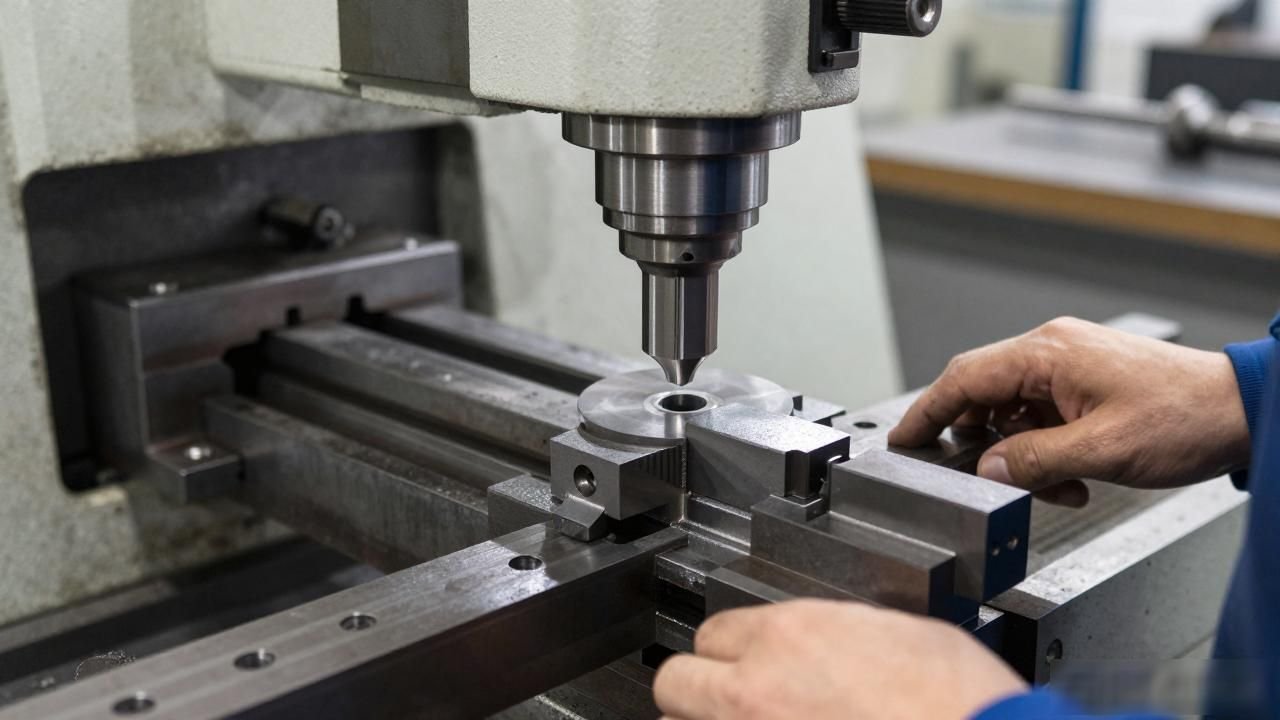
When processing the end face of the hole, you can use the universal tool holder to perform the boring plane action. The advantage of this is that it can ensure a higher perpendicularity between the hole and the end face, and can also make the surface roughness finer.
However, its limitations are also obvious. After all, the plane area that can be processed is very limited, and the amount of tool backing each time is very small. The feed operation mainly relies on the radial movement of the tool holder, which results in low system rigidity, so it is not suitable for milling those long planes.
During the operation phase, as long as the control button of the automatic tool holder is clicked, the tool holder can perform automatic displacement in the radial direction. Then, you need to carefully insert the ejector pin into the hole corresponding to the scale ring, and hold it firmly by hand. In this way, the automatic displacement function of the lateral position will be activated.
When you observe that the specific marked line on the scale ring is completely aligned with one of the numerical scales, this value clearly represents the specific movement distance of the tool holder in the radial direction during the spindle rotation for a full circle . Boring processing accuracy guarantee method Boring processing accuracy guarantee method , so be sure to remember this reading carefully and deeply.
Tool nose secondary deflection angle and tool holder rigidity
During the process of installing the boring tool, the specific numerical standard of the secondary deflection angle cannot be less than 4 degrees. If the angle is smaller, the secondary flank surface will rub against the surface that has been processed, and the direct result is that the roughness will become very rough.
In the specific operation scenario of using a universal tool holder for machining, this specific detail is particularly easy to be ignored. Well, before officially loading the tool, take out an angle ruler to measure it. This step is actually effortless at all. Don't omit this crucial step just because you want to save trouble.
It is recommended that when choosing a knife holder, you should try to choose a thick and short style. Because such a tool holder has better rigidity, the vibration generated during the cutting process will be smaller, so the surface quality will become more stable.
Everyone knows that the rigidity of the universal tool holder itself is not too high. If the tool holder is designed to be more slender, it will be easier for the tool to give way. The milled plane can easily produce wrinkles, and the accuracy cannot maintain stability at all. Therefore, using a thick and short tool holder can be said to be a basic operating requirement.
When you are actually performing plane milling operations with a universal tool holder, have you ever encountered a situation where the tool holder is vibrating and causing the tool to break? Please describe how you solved this problem in the comment area. If you think this method is really useful, then give it a like and forward it to your workshop colleagues.
Leave a Reply
You must be logged in to post a comment.