
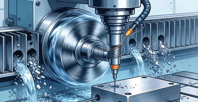
The feeding direction of the carbide milling cutter relative to the workpiece and the rotation direction of the milling cutter mainly include:
Many CNC masters have encountered this situation: even though the speed feed is fine, the blade is inexplicably chipped and the machined surface looks like a dog gnawing. The problem most likely lies in the milling method – down milling or up milling has not been chosen correctly. For carbide milling cutters, this choice directly determines tool life and processing quality.
What is the difference between down milling and up milling?
When performing down milling, the rotation direction of the milling cutter is exactly the same as the given direction of travel of the workpiece. You can feel that the cutter and the workpiece are moving in the same direction. Once the cutter touches the workpiece, it cuts directly into the workpiece, and cuts from the thick body to the thin body area. The first cut is the maximum cutting thickness. This cutting method is very clean and simple, without any hesitation and procrastination.
The situation of up milling is exactly the opposite. The direction of rotation of the tool is opposite to the direction of travel of the workpiece. The knife needs to rub a certain distance on the surface of the workpiece before it can start the real cutting action, and it cuts from thin to thick. The thickness of the chip is almost zero at the beginning, and it will not reach the maximum thickness until the end. This is just like when you want to cut a piece of meat, the knife does not cut directly downwards, but pushes forward and slides a certain distance before cutting.
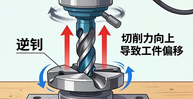
The cutting force direction is completely different
If it is in the down milling state, the cutting force will be vertically downward, which will firmly press the workpiece on the workbench. This is a hard material CNC machining technique that is of great benefit to the clamping operation. The workpiece will become more stable during the cutting process, which is not allowed at all. It is easy to produce vibrations, especially when the feed direction of the carbide milling cutter relative to the workpiece and the rotation direction of the milling cutter are important for processing thin-walled parts, or when a strong suction cup is used, down milling can significantly reduce the risk of the workpiece becoming warped.

The situation in up milling is exactly the opposite. The cutting force is in the upward lifting direction, with the purpose of pulling the working items up from the working table. If the object you are working on is not firmly clamped, or if a magnetic suction cup is used, it is very easy to lift the object during up milling. In this way, this explains why sometimes the working items suddenly shift in position during the milling operation. It is most likely that the tool lifting force generated by the up milling is causing the problem.
Why down milling is preferred in most cases
In terms of cutting effect, down milling has absolute advantages. This is because once the blade hits the workpiece, it will start cutting the thick part, its cutting force is in a stable state, and the machined surface has a high smoothness. Moreover, the chips of down milling change from thick to thin. When the blade leaves the workpiece, the cutting force is minimal, so no burrs or scratches will be left on the surface of the workpiece.
In actual machining, the heat generated by down milling is easier to be carried away through the chips . CNC machining techniques for hard materials . The chips are formed when they are thickest, when the heat is most significant. The chips fly straight away without accumulating on the surface of the workpiece. This is why the parts processed by down milling have higher dimensional accuracy and the surface is more beautiful.
When do you have to choose reverse milling?
Although down milling has advantages, the lead screws of some old milling machines have reverse clearance. During down milling operations, the cutting force will pull the workbench forward. If the clearance between the lead screw is too large, the workbench will suddenly jump forward, causing the tool to dig in and break the edge. In this case, upcut milling can only be used, because the cutting force during upmilling pushes the workbench back, which can actually eliminate the gap.
There is another situation, that is, there is hard skin or oxide layer on the surface of the blank. In this regard, during down milling, the first knife is cut from the thickest part. If there are hard spots on the surface, the impact will be particularly large. However, in up milling, it is lightly rubbed first, and then slowly cut deeper. This can reduce the impact on the blade. Therefore, when processing the black leather surface of castings or forgings, sometimes up milling is used first to remove the hard skin.
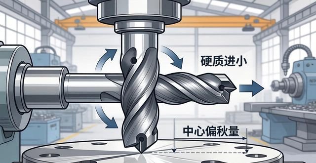
The detail of milling cutter center offset is critical
Many people don't know that the axis line of the milling cutter cannot be facing the center line of the workpiece, it must be slightly offset. If the tool is aligned with the center for cutting, then when the insert enters and exits the workpiece, the direction of the radial cutting force will change back and forth, causing the spindle to vibrate. If it is a mild case, the processing surface will become rough, and if it is serious, the blade will be directly broken.
Offset the axis of the milling cutter to one side. This is the correct approach. The offset is about 5% to 10% of the diameter of the milling cutter. When it becomes a preload in a constant direction and the cutting force is within the radial direction, the milling cutter seems to be pushed steadily by a force, so there is no back and forth swing. Especially important during finishing, this technique can significantly improve surface quality.
The tool selection and tool path must also be coordinated well.
The diameter of the milling cutter should be slightly larger than the width of the workpiece. This is because once the diameter increases, the angle of the blade will become smaller during the cutting process, and the frequency of cutting in and out will decrease. In this way, the number of impacts suffered by the blade can be reduced. For example, in the case of processing a plane with a width of 40 mm, it is more reasonable to choose a 50 mm milling cutter than a 32 mm milling cutter.
When actually programming, the position of the cutting edge cutting into the workpiece needs to be considered, and the blade should be cut from the outside of the workpiece as much as possible to prevent cutting from the middle. Because when cutting from the middle, the blade will bear forces from multiple directions at the same time, which can easily lead to chipping. In addition, when down milling, pay attention to whether the chips will be brought back by the blade for re-cutting. If necessary, coolant should be turned on to flush away the chips.
Finally, I have a question for you: When processing stainless steel or hardened steel, have you ever encountered a situation where the blade suddenly broke due to incorrect selection of down milling or reverse milling? What size milling cutter was used and what parameters were used? Welcome to share your practical experience in the comment area, so that more colleagues can avoid detours. If you find this article useful, please give it a like and forward it to the workers in the workshop who are still debating whether to choose between down milling or reverse milling.


暂无评论内容